
Installation Guide


Page 8 of 9
It is important to understand that each tub has variations and modifications maybe necessary in the field.
1.
It may be necessary to adjust the Support Box structure according to the conditions present during your
installation. For example, for wooden sub- floors, begin by screwing or gluing a treated 2x4 directly to
the sub-floor to serve as the base for our support structure. For concrete floors, a treated 2x4 is adhered
directly to the concrete floor with adhesive. The 2x4 might need to be cut into several sections if there is
a support brace in the cut out channel.
2.
Build the Support Box structure to appropriate height. If working with a concrete sub-floor,
thoroughly inspect and clean the floor in the tub cut out channel prior to securing the treated 2x4.
Remove any materials from the concrete that may cause an uneven surface. Apply adhesive
directly to the concrete floor. Insert the 2x4’s and thoroughly spread the adhesive on the concrete.
3.
If wood sub-floor is present, screw the 2x4 directly to the sub-floor.
4.
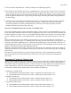
Prior to inserting the small Support Box, it is first necessary to secure a 22 ½” long 2x4 into the channel
of the small Support Box. Place a bead of adhesive around the inside of the Support Box and insert the
2x4. Place several screws into the small Support Box to properly adhere the 2x4 into proper position.
Small Support Box
FIGURE 7
5.
Insert the small box in the channel. At this point, do not adhere the small support box to anything. Place
the large support box into the channel and over the top of the small box. Place the CleanCut Step into
position and compress the CleanCut Step downward to determine the proper height and placement for
the support box structure.
6.
Once the support of the CleanCut Step has been achieved, remove the Step and mark both the left and
right ends of the small box where the large box is compressed while the boxes are in the tub opening
channel. Once properly marked, remove both support boxes and label the markings “Left” and “Right”
to avoid potential confusion. Uncompress the two support boxes from one another and begin the process
to permanently adhere the boxes in proper position.
7.
Apply adhesive around the perimeter of the large box. Compress the small and large support box
structures back together to the appropriate markings made earlier on the small box. Place the support
structure back into the channel and insert the CleanCut Step to verify that proper placement has been
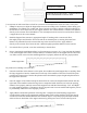
achieved. Secure both sides of the support structure by placing two screws in each side (Figure 8).
FIGURE 8
1 ¼” Dry Wall Screws
CLEAN CUT STEP
SUPPORT BOX STRUCTURE – LARGE SUPPORT
BOX COMPRESSED ON SMALL BOX
BASE 2X4 AFFIXED TO FLOOR, IF NECESSARY
Dry Wall Screws Holding 2x4s (each side)
FIGURE 6