CLEANCUT ULTRA-LOW INSTALLATION GUIDE COPYRIGHT © 2017 SAFEWAY SAFETY STEP, LLC (DBA “CleanCut”) All Rights Reserved Reproduction or Distribution of this Installation Manual is Strictly Prohibited VIDEO INSTRUCTIONS CAN BE VIEWED AT cleancutbath.
Page 2 of 10 IMPORTANT – PLEASE WATCH VIDEO PRIOR TO READING DIRECTIONS AND BEFORE BEGINNING INSTALLATION IT IS VERY IMPORTANT THAT ALL INSTRUCTIONS IN THE INSTALLATION MANUAL ARE FOLLOWED THOROUGHLY. VIDEO INSTRUCTIONS CAN BE VIEWED AT cleancutbath.com INSTALLATION OF THE CLEANCUT ULTRA-LOW REQUIRES USE OF POTENTIALLY DANGEROUS TOOLS.
Page 3 of 10 Thank you for your interest in the CleanCut Ultra-Low. This installation manual includes an overview of the CleanCut Ultra-Low installation kit as well as instructions pertaining to the step-by-step instructions for CleanCut Ultra-Low installation.
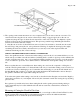
Page 4 of 10 Preparing the Tub 1. Before beginning any work, it is important to inspect the tub for existing chips, markings or other types of damage. It is always wise to make the owner or manager aware of any existing damage prior to beginning the installation process. 2.
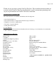
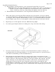
Page 5 of 10 FIGURE 1 4. The opening for the CleanCut Ultra-Low is now completed and you can remove the cut-out section. Use caution when removing the cut-out section as there may be sharp or jagged edges both on the cut-out segment and along the edges of where the cuts were made on the sides of the tub. It is helpful to spend a moment to file down any potential hazard areas. This prevents potential snags with fitting the CleanCut Ultra-Low and reduces the risk of injury. 5.
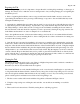
Page 6 of 10 Large/Wide CleanCut Ultra-Low • The maximum top rail measurement to order a large/wide CleanCut Ultra- Low is 6.25”. Sizing Note – Due to the design enhancement of more rounded corners on the top of the Ultra-Low product, to be able to install on a bathtub with a top measurement of 6.0” you must measure down 1” from the top of the step to begin tracing you template on the side of the step. • The maximum bottom measurement to order a large/wide CleanCut Ultra- Low is 7.25”. 1.
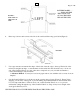
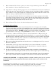
1” Page 7 of 10 FIGURE 3 SIDE VIEW OF LEFT END OF STEP 6. PATTERN MARKS - - - - - - INDICATE THE AREA TO BE CUT OUT ON THE LEFT END OF THE STEP. Place step as shown and connect each side of the outside tub line using a yard stick (Figure 4). FIGURE 4 7. Use a tape measure and transfer the shape of the inside of the tub edge to the step. The inside of the tub may be irregular in shape, so measurements for the inside line must be made every 3” from one end of the CleanCut Ultra-Low to the other.
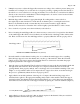
Page 8 of 10 FIGURE 5 It is required that proper eye protection be worn while using the jigsaw. Cut directly on the center of the traced lines. Upon reaching the corners while cutting, tilt the jigsaw outward to prevent cutting past your lines on the vertical ends of the CleanCut Ultra-Low. Remember to tilt your blade on each corner, cutting all areas that have been marked. 9. Place the CleanCut Ultra-Low into position. Remember, the straight face of the CleanCut Ultra-Low is on the outside of the tub.
Page 9 of 10 1. It may be necessary to adjust the Support Box structure according to the conditions present during your installation. For example, for wooden sub- floors, begin by screwing or gluing a treated 2x4 directly to the sub-floor to serve as the base for our support structure. For concrete floors, a treated 2x4 is adhered directly to the concrete floor with adhesive. The 2x4 might need to be cut into several sections if there is a support brace in the cut out channel. 2.
Page 10 of 10 9. Place the CleanCut Ultra-Low into position once more to inspect the fit and position. This is the final opportunity to make any adjustments if necessary. 10. Apply adhesive to the top of the large support box. It is recommended that an extra bead of adhesive be placed on the ends of the large support box as the Step curves up toward the ends. Place a substantial bead of adhesive on the top left and right side of the tub where the CleanCut Ultra-Low will be seated.