CLEAR-COM ENCORE FL-7 CALL SIGNAL FLASHER INSTRUCTION MANUAL
FL-7 Call Signal Flasher Instruction Manual © 2007 Vitec Group Communications Ltd. All rights reserved. Part Number 810495Z Rev. 1 Vitec Group Communications, LLC. 850 Marina Village Parkway Alameda, CA 94501 U.S.A Vitec Group Communications 7400 Beach Drive Cambridge Research Park Cambridgeshire United Kingdom CB25 9TP Vitec Group Communications Room 1806, Hua Bin Building No. 8 Yong An Dong Li Jian Guo Men Wai Ave Chao Yang District Beijing, P.R.
CONTENTS OPERATION . . . . . . . . . . . . . . . . . . . . . . . . . . . . . . . . . . . . . . . 1-1 Introduction . . . . . . . . . . . . . . . . . . . . . . . . . . . . . . . . . . . . . . . . . . . . . . . . . 1-1 Operation . . . . . . . . . . . . . . . . . . . . . . . . . . . . . . . . . . . . . . . . . . . . . . . . . . . 1-1 Installation . . . . . . . . . . . . . . . . . . . . . . . . . . . . . . . . . . . . . . . . . . . . . . . . . . 1-2 Mounting . . . . . . . . . . . . . . . . . . . . . . . . . . .
ii FL-7 CALL SIGNAL FLASHER
IMPORTANT SAFETY INSTRUCTIONS 1. 2. 3. 4. 5. 6. 7. Please read and follow these instructions before operating this product. 8. 9. 10. 11. 12. 13. Read these instructions. Keep these instructions. Heed all warnings. Follow all instructions. Do not use this apparatus near water. Clean only with dry cloth. Do not block any ventilation openings. Install in accordance with the manufacturer’s instructions.
CAUTION RISK OF ELECTRIC SHOCK DO NOT OPEN This symbol alerts you to the presence of uninsulated dangerous voltage within the product's enclosure that might be of sufficient magnitude to constitute a risk of electric shock. Do not open the product's case. This symbol informs you that important operating and maintenance instructions are included in the literature accompanying this product.
1 OPERATION INTRODUCTION Congratulations on choosing this Clear-Com product. Clear-Com was established in 1968 and remains the market leader in providing intercoms for entertainment, educational, broadcast and industrial applications. The ruggedness and high build-quality of Clear-Com products defines the industry standard. In fact, many of our original beltpacks and main stations are still in daily use around the world.
INSTALLATION MOUNTING The Call Signal Flasher is designed for either portable use or permanent installation. It can be placed atop a table, shelf or other equipment. It may also be mounted on a wall. Keyhole slots are provided on the underside of the unit for wall mounting. Use #6 screws and wall anchors as appropriate. The diagram below provides wall drilling and mounting details.
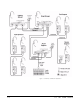
Manager can communicate with the Lighting Director or the House Engineer on Channels A or B, or with the Monitor Engineer on Channel B. The Lighting Director uses a 2-Channel Remote Station to communicate with the Spot Operators on Channel A. The House Engineer also uses a 2-Channel Remote Station and communicates with the Monitor Engineer and Tech Support people on Channel B.
Figure 1-3: Example Call Flasher Application 1-4 FL-7 CALL SIGNAL FLASHER
2 TECHNICAL SPECIFICATIONS FL-7 CALL SIGNAL FLASHER Flash Rate Flasher Lens Rear Panel Connectors Power Requirements Input Voltage: Input Current: (idle) Input Current (max) Front Panel Controls & Indicators Environmental Dimensions Weight 2 times/sec 2.5" diameter red One each XLR-3F and XLR-3M 20-30 VDC <= 10mA <= 90mA Brightness Control Three-way switch for flash and tone Tone level control Speaker 32o to 122o F (0o to 50o C) H 2.5" W 4" D 5.0" (63 x 101 x 127 mm) 0.91 lbs. (0.
2-2 FL-7 CALL SIGNAL FLASHER
LIMITED WARRANTY Vitec Group Communications (VGC) warrants that at the time of purchase, the equipment supplied complies with any specification in the order confirmation when used under normal conditions, and is free from defects in workmanship and materials during the warranty period. VGC offers 24 x 7 customer support if you have an Extended Warranty or Service Contract. Return Material Authorization (RMA) numbers are required for all returns. Both warranty and non-warranty repairs are available.
such agreement. For more information, contact your authorized dealer, distributor, or sales representative. Instructions for reaching VGC’s User Support Centers are given below. Telephone for Europe, Middle East and Africa: +49 40 6688 4040 Telephone for the Americas and Asia: +1 510 337 6600 Email: vitec.support@AVC.de Once the standard warranty period has expired, the User Support Center will continue to provide telephone support if you have purchased an Extended Warranty or Service Contract.
years the warranty of any product offered with a standard two-year warranty. The total warranty period will not extend beyond five years. Any purchase of an extended warranty provides 24 x 7 customer support in addition to the warranty immediately upon purchase of the warranty extension. Note: VGC does not offer warranty extensions on UHF wireless intercom systems, or on any product with a 1-year or 90-day warranty.
of customer furnished components resulting in damage to VGC provided product. This limited warranty is not transferable and cannot be enforced by anyone other than the original consumer purchaser. This warranty gives you specific legal rights and you may have other rights which vary from country to country.