CLEAR-COM ECLIPSE BAL-8 TRANSFORMER GROUND ISOLATION INTERFACE INSTRUCTION MANUAL
BAL-8 Ground Isolation Interface Instruction Manual © 2008 Vitec Group Communications Ltd. All Rights Reserved. Part Number 810403Z Rev. 1 Vitec Group Communications LLC 850 Marina Village Parkway Alameda, CA 94501 U.S.A Vitec Group Communications Ltd 7400 Beach Drive IQ Cambridge Cambridgeshire United Kingdom CB25 9TP Vitec Group Communications Room 1806, Hua Bin Building No. 8 Yong An Dong Li Jian Guo Men Wai Ave Chao Yang District Beijing, P.R.
CONTENTS OPERATION . . . . . . . . . . . . . . . . . . . . . . . . . . . . . . 1-1 Description . . . . . . . . . . . . . . . . . . . . . . . . . . . . . . . . . . . . . . . . . . . . 1-1 Control, Indicators and Connectors . . . . . . . . . . . . . . . . . . . . . . . . . 1-2 INSTALLATION . . . . . . . . . . . . . . . . . . . . . . . . . . . . 2-1 Installation in a Matrix . . . . . . . . . . . . . . . . . . . . . . . . . . . . . . . . . . . . 2-1 MAINTENANCE. . . . . . . . . . . . . . . . . . . . . . . . .
2 Vitec Group Communications BAL-8 Ground Isolation Interface Instruction Manual
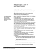
IMPORTANT SAFETY INSTRUCTIONS For your safety, it is important to read and follow these instructions before operating a BAL-8 Ground Isolation Interface. (1) WARNING: To reduce the risk of fire or electric shock, do not expose a BAL-8 Ground Isolation Interface to rain or moisture. Do not operate a BAL-8 Ground Isolation Interface near water, or place objects containing liquid on it. Do not expose a BAL-8 Ground Isolation Interface to splashing or dripping water.
Please familiarize yourself with the safety symbols in Figure 1. When you see these symbols on a BAL-8 Ground Isolation Interface, they warn you of the potential danger of electric shock if the station is used improperly. They also refer you to important operating and maintenance instructions in the manual.
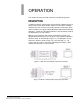
1 OPERATION This chapter describes the BAL-8 Interface and how to operate it. DESCRIPTION The BAL-8 provides eight channels of transformer isolation for up to 8 direct interface ports to the Eclipse matrix. The transformer isolation eliminates the hum and noise caused by ground or earth loops. Each channel handles four signals (two bi-directional audio and two RS-422 data lines). Only the bi-directional audio lines are transformer isolated; the RS-422 lines are not isolated.
CONTROL, INDICATORS AND CONNECTORS The only controls on the unit are the slide switches to select between Normal and Interface modes. The BAL-8 does not have any indicators. All 16 of the unit’s RJ-45 connectors are on the back panel. Each channel has one Input and one Output connector.
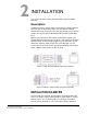
2 INSTALLATION This chapter describes how to install the BAL-8 ground isolation interface. Description The BAL-8 provides eight channels of transformer isolation for direct interface ports on the Eclipse matrix. The transformer isolation eliminates the hum and noise caused by ground loops. Each channel handles four signals (two bi-directional audio and two RS-422 data lines).
Output port in one of the BAL-8’s channels and the other connecting the same channel’s Input port to the intended destination equipment. One linking option is to connect the last eight ports of a Clear-Com matrix to the eight Output ports on the BAL-8 as shown in Figure 2-3. Each of the BAL-8’s Input ports can then be connected to destination equipment. Each channel can operate in either Normal or Interface mode.
3 MAINTENANCE This chapter provides maintenance information for the BAL-8 and how to install it. DESCRIPTION The BAL-8 provides eight channels of transformer isolation for direct port interfaces to the Eclipse matrix. The transformer isolation eliminates the hum and noise caused by ground loops. Each channel handles four signals (two bi-directional audio and two RS-422 data lines).
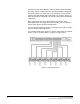
A Channel 5 3 6 1 2 3 4 5 6 7 8 T2 TTPC-1 1 4 2 5 3 6 4 J1A RJ-45 2 INPUT (EQUIPMENT) J1B RJ-45 6 1 2 3 4 5 6 7 8 T1 TTPC-1 1 4 5 OUTPUT FROM (FRAME) 3 2 1 S1 Figure 3-3: One Channel in a BAL-8 Circuit Board SPARES FOR BAL-8 MAIN PCB DEVICE Transformer 3-2 DESCRIPTION 600CT/600CT PART NO.
WARRANTY Clear-Com guarantees this product to be free of manufacturing defects in material and workmanship under normal use for a period of two years from the date of purchase. TECHNICAL SUPPORT Clear-Com offers 24/7 customer support. Return authorization numbers are required for all returns. To ensure complete and timely support to its customers, Clear-Com maintains Technical Service Centers (TSC) staffed by qualified technical personnel.
WARRANTY REPAIRS While Clear-Com will ensure complete system integrity by providing whatever support is necessary to resolve any failure covered under the terms of the warranty, the normal procedure will be to repair or replace any defective Line Replaceable Unit (LRU) that is returned to Clear-Com during the warranty period. A Line Replaceable Unit (LRU) is defined as: an assembly that can be safely removed from the system and readily replaced by plugging in a new unit.
for consumables and other supplies), or guarantees, expressed or implied (including, without limitation, any warranties of merchantability or fitness for a particular purpose), of any nature whatsoever, whether arising in contract, tort, negligence of any degree, strict liability or otherwise, with respect to the products or any part thereof delivered hereunder and/or with respect to any non-conformance or defect in any such product and/or part thereof delivered hereunder and/or with respect to any non-conf
W-iv WARRANTY