GPI-6 GENERAL PURPOSE INPUTS INTERFACE INSTRUCTION MANUAL
GPI-6 General Purpose Inputs Interface Instruction Manual © 2008 Vitec Group Communications Ltd. All rights reserved. Part Number 810309Z Rev. 3 Vitec Group Communications LLC 850 Marina Village Parkway Alameda, CA 94501 U.S.A. Vitec Group Communications Ltd 7400 Beach Drive Cambridge Research Park Cambrideshire United Kingdom CB25 9TP Vitec Group Communications Room 1806, Hua Bin Building No. 8 Yong An Dong Li Jian Guo Men Wai Ave Chao Yang District Beijing, P.R.
CONTENTS OPERATION . . . . . . . . . . . . . . . . . . . . . . . . . . . . . . 1-1 Introduction. . . . . . . . . . . . . . . . . . . . . . . . . . . . . . . . . . . . . . . . . . . . 1-1 Description . . . . . . . . . . . . . . . . . . . . . . . . . . . . . . . . . . . . . . . . . . . . 1-1 Operation . . . . . . . . . . . . . . . . . . . . . . . . . . . . . . . . . . . . . . . . . . . . . 1-2 Configuration . . . . . . . . . . . . . . . . . . . . . . . . . . . . . . . . . . . . . . . . . . 1-2 INSTALLATION.
ii Vitec Group Communications GPI-6 Interface Instruction Manual
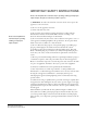
IMPORTANT SAFETY INSTRUCTIONS Please read and follow these instructions before operating a GPI-6 general purpose inputs interface. Keep these instructions for future reference. (1) WARNING: To reduce the risk of fire or electric shock, do not expose this apparatus to rain or moisture. (2) Do not use the apparatus near water. (3) Clean only with a dry cloth. Please read and follow these instructions before operating a GPI-6 general purpose inputs interface. (4) Do not block any ventilation openings.
CAUTION RISK OF ELECTRIC SHOCK DO NOT OPEN This symbol alerts you to the presence of uninsulated dangerous voltage within the product's enclosure that might be of sufficient magnitude to constitute a risk of electric shock. Do not open the product's case. This symbol informs you that important operating and maintenance instructions are included in the literature accompanying this product.
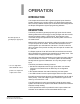
1 OPERATION INTRODUCTION This chapter describes the GPI-6 general-purpose inputs interface. System operators can use this chapter once the Eclipse system has been correctly installed and the input controls have been assigned with the Eclipse Configuration System programming software. DESCRIPTION The GPI-6 provides six general-purpose logic inputs.
The front panel of the GPI-6 has six green LEDs to indicate the presence of an input signal on a given channel. A seventh yellow LED indicates that the module is communicating with the matrix. There is also a TEST pushbutton switch for each input to allow local activation of the software function in the matrix that the input is controlling. OPERATION Once the GPI-6 is installed and configured there are no controls for day-to-day operation. Activation of each individual input is indicated by LEDs.
2 INSTALLATION INTRODUCTION This chapter describes the installation of the GPI-6 general purpose inputs interface and wiring to the external devices. The GPI-6 occupies one slot in an interface frame. Connections are made to the matrix and other modules via an 8-pin RJ-45 connector, and to the external devices via two DB-9M connectors. There are no adjustment controls for the GPI-6.
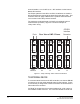
second interface 1 to 6 for GPI 2, etc. GPI interface 0 is the internal Matrix GPI interface. For Eclipse systems if both GPI-6 and RLY-6 interfaces are used the GPI-6 interfaces are required to be placed first in the daisy chain. This restriction does not apply to Matrix Plus 3 systems where interfaces can be mixed in this 'daisy-chained' scheme. The maximum combined length of all the RJ-45 cables should not exceed 20 feet (6 meters). Figure 2-1 shows an example of “daisy-chain” wiring.
inputs 4-6. In Figure 2-2 the labels on the pins apply to either connector. 1 6 #1/4 Input A #1/4 Input B 2 #2/5 Input A #2/5 Input B 7 3 8 #3/6 Input A #3/6 Input B 4 9 Ground Power Source 5 Ground Figure 2-2: GPI-6 Interface DB-9M Connector Pinout Figure 2-3: GPI-6 Application Examples The two illustrations in Figure 2-3 show how to connect switches or contacts using the power source provided by the GPI-6 module or powering switches from external sources.
2-4 Vitec Group Communications GPI-6 Interface Instruction Manual
3 SPECIFICATIONS Input Type Quantity Voltage Range Input Current DC Isolation Opto-Isolated current limited 6 5 - 45 volts DC 4 - 7 mA 10 mega-ohms Module Power Supply Requirements Voltage Required Current Required Connectors Input Connections Matrix Connection Indicators and Controls LED Indicators Pushbutton Switches 8 – 10 volts DC <20 mA 2 ea. DB-9M 2 ea. RJ-45 ea.
3-2 Vitec Group Communications GPI-6 Interface Instruction Manual
LIMITED WARRANTY Vitec Group Communications (VGC) warrants that at the time of purchase, the equipment supplied complies with any specification in the order confirmation when used under normal conditions, and is free from defects in workmanship and materials during the warranty period.
Telephone for Europe, Middle East and Africa: +49 40 6688 4040 or +44 1223 815000 Telephone for the Americas and Asia: +1 510 337 6600 Email: vitec.support@AVC.de Once the standard warranty period has expired, the User Support Center will continue to provide telephone support if you have purchased an Extended Warranty. For latest contact information please refer to the Service and Support section at www.clearcom.com.
EXTENDED WARRANTY You can purchase an extended warranty at the time of purchase or at any time during the first two years of ownership of the product. The purchase of an extended warranty extends to five years the warranty of any product offered with a standard two-year warranty. The total warranty period will not extend beyond five years. Note: VGC does not offer warranty extensions on UHF wireless intercom systems, or on any product with a 1-year or 90-day warranty.
This limited warranty is not transferable and cannot be enforced by anyone other than the original consumer purchaser. This warranty gives you specific legal rights and you may have other rights which vary from country to country.