KB-211/KB-211GM TWO-CHANNEL SPEAKER STATIONS USER MANUAL
Clear-Com Intercom Systems KB-211/KB-211GM Two-Channel Speaker Stations Introduction Congratulations and thank you for choosing this Clear-Com product. The KB-211 and KB-211GM Two-Channel Speaker Stations are powerful, user-friendly units that can serve as versatile intercom stations. Please read this manual completely to better understand the functions of these products. For questions not addressed in this manual, contact the dealer or Clear-Com directly.
KB-211/KB-211GM Two-Channel Speaker Stations Clear-Com Intercom Systems plug-on screw terminal strip. Male and female three-pin XLR connectors are provided on the V-Box for an in-line connection to one of the intercom channels. The optional EB-TW daughter board module can be installed to provide an interface to two intercom channels on a single microphone cable.
Clear-Com Intercom Systems 11 KB-211/KB-211GM Two-Channel Speaker Stations 12 8 2 A VOX 9 4 3 B Channel Select Panel Mic Call Intercom Level Headset Program Level Off Sidetone On Talk PL Speaker pro KB-211GM Speaker S tat ion 10 5 1 7 6 FIGURE 1: Front Panel 1—Talk Button and Lamp The Talk button activates the microphone feed to the selected intercom channel. The Talk button has a dual action (momentary or latching) depending upon how the button is pressed.
KB-211/KB-211GM Two-Channel Speaker Stations • Clear-Com Intercom Systems Speaker Dip—If the front-panel speaker is turned on and the VOX feature is not used, pressing the Talk button will reduce the speaker output level to avoid feedback. 2—Call Button and Lamp Pressing the Call button will send a call signal on the selected channel. All the call lights on that channel will then flash. Call signals can also be sent while talking if required.
Clear-Com Intercom Systems KB-211/KB-211GM Two-Channel Speaker Stations 1. Set the VOX control fully counterclockwise to disable this feature. (KB-211GM only) 2. Set the Intercom Level control to a comfortable level. 3. Press the Talk button and speak into the microphone while turning the Sidetone control slowly back and forth. There should be a point where the operator’s voice (and any accompanying acoustic feedback) disappears. This is the null point. 4. Readjust the VOX control.
KB-211/KB-211GM Two-Channel Speaker Stations • Clear-Com Intercom Systems Pin 4—headphone hot. The microphone and headphone wiring in the headset cord must be individually shielded. Note: Do not connect Pins 1 and 3 together. Headset extension cords or headset ”Y” cables are not recommended because they may increase crosstalk between channels. 11—Panel Mic Connector (KB-211GM only) Clear-Com recommends the GM-9 (9 in. long) and GM-18 (18 in. long) plug-in panel microphones be used with the KB-211GM.
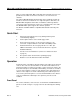
Clear-Com Intercom Systems KB-211/KB-211GM Two-Channel Speaker Stations 18 P2 Must be installed if no option 17 P3 Must be installed if no option P1 Call on Both P1 Call on Selected 15 16 View from top of KB-211 1 2 3 Front Panel 13 14 FIGURE 2: Internal Adjustments and Connections 13—Call Alert Tone Level Control This control adjusts the volume of the Call Alert Tone sound. This is normally adjusted when the system is set up and shouldn’t need to be adjusted during normal operation.
KB-211/KB-211GM Two-Channel Speaker Stations Clear-Com Intercom Systems 1—Single Channel In some installations, the KB-211 is intended to be used only with one intercom channel. Setting the Single Channel switch to the ON position will connect the KB-211 to the one intercom channel regardless of the position of the front-panel Channel selector. Note: In two-channel installations, this switch must be set to the OFF position. 2—Long Line If a long cable run is unavoidable and approaches 700 ft.
Clear-Com Intercom Systems KB-211/KB-211GM Two-Channel Speaker Stations Pin 1 2 3 Channel A 1 XLR Connector KB-211 Intercom Connector FIGURE 3: One-Channel Cable Wiring 2 Pin 1 3 Channel A 3 Channel B 1 2 1 KB-211 Intercom Connector XLR Connectors FIGURE 4: Two-Channel Cable Wiring 17—Program Input A three-terminal, plug-on connector provides the program input to the station. Program is fed to the headset and speaker.
KB-211/KB-211GM Two-Channel Speaker Stations Clear-Com Intercom Systems Program Input Cable Wiring: Pin 1 2 3 1 KB-211 Program Input Connector XLR Connector FIGURE 5: Program-Input Cable Wiring 18—Option Board Jumpers The three jumper plugs P1, P2, and P3 must be installed when optional modules are not used. When the optional EB-4W or EB-TW modules are used, both P1 and P3 must be removed. In the KB-211GM, P2 is replaced by the VOX module. Save these jumper plugs for possible future use.
Clear-Com Intercom Systems KB-211/KB-211GM Two-Channel Speaker Stations EQ/ LIM Sidetone Null Intercom Volume Headset Mic Speaker Speaker On/Off Speaker Dip Mic Mute Long Line Headset Output Talk Talk Program Mute Call Alert Tone Level Microprocessor Call Latch Disable Program Level Call Light Single Chan. Call Send & Receive Power RMK Channel Switch TW Option Balanced Program Input Common +30 VDC Ch. B Ch. A Ground Ch. B 4-Wire Input 16 VAC Rectifier Ch.
KB-211/KB-211GM Two-Channel Speaker Stations Headset Mic EQ/ LIM Clear-Com Intercom Systems Sidetone Null Intercom Volume Mic Select Speaker Speaker On/Off Speaker Dip Panel Mic Mic Dip / Mute Long Line Headset Output VOX Talk/ VOX Talk Program Mute Red / Green Call Alert Tone Level Microprocessor Call Latch Disable Program Level Call Light Single Chan. Call Send & Receive Power RMK Common +30 VDC Ch. B Ch. A Ground Channel Switch TW Option Balanced Program Input Ch.
Clear-Com Intercom Systems KB-211/KB-211GM Two-Channel Speaker Stations Scenario 2 The KB-211 has an internal failure. Solution: Unit requires servicing. • Speaker does not operate, but the Talk Light comes on when Talk button is pressed. Scenario 1 The Speaker switch is turned off, the volume knob is turned all the way down, or the channel switch is set to the unused channel. Solution: Adjust controls appropriately. Scenario 2 The speaker plug or wiring has come loose.
KB-211/KB-211GM Two-Channel Speaker Stations Clear-Com Intercom Systems Solution: If only one intercom line is connected, set Option Switch 1 to the ON or CLOSED position to link both channel switch positions to the same intercom line. Scenario 5 A headset extension cord was used. Solution: Headset extension cords are not recommended. • VOX problems (KB-211GM only) Scenario 1 VOX stays tripped (red light on) or the sensitivity is set too high.
Clear-Com Intercom Systems • KB-211/KB-211GM Two-Channel Speaker Stations The call signal does not function. Scenario 1 Excessive DC loading of intercom line. Solution: Remove any audio transformers or other equipment that may be connected across the intercom line. If equipment other than Clear-Com intercom equipment must be connected to the intercom line, please contact Clear-Com application or service personnel for information or recommendations.
KB-211/KB-211GM Two-Channel Speaker Stations Clear-Com Intercom Systems Parts Lists Parts List for the KB-211 / KB-211GM Main PCB and Chassis Capacitors Value 220 .01 22 4.7 4.7 .047 100 22 47 220 470 .0022 .0047 .01 uF uF uF uF uF uF uF pF pF pF pF uF uF uF Type Aluminum Ceramic Disc Tantalum Tantalum Aluminum NP Mylar Aluminum Ceramic Disc SMD Ceramic Disc SMD Ceramic Disc SMD Ceramic Disc SMD Ceramic Disc SMD Ceramic Disc SMD Ceramic Disc SMD Voltage 35V 1.
Clear-Com Intercom Systems 8.25K 12.1K 15.0K 20.0K 56.2K 100K 121K 475K 1.
KB-211/KB-211GM Two-Channel Speaker Stations Switch Switch Switch Switch Wire DPDT P.B.
Clear-Com Intercom Systems KB-211/KB-211GM Two-Channel Speaker Stations FIGURE 8: Main PCB Component Layout © Clear-Com Intercom Systems 1999 19 Rev.
KB-211/KB-211GM Two-Channel Speaker Stations Clear-Com Intercom Systems This page is a place holder. Rev.
FIGURE 9: KB-211 Schematic © Clear-Com Intercom Systems 1999 21 Rev.
KB-211/KB-211GM Two-Channel Speaker Stations Clear-Com Intercom Systems This page is a place holder. Rev.
Clear-Com Intercom Systems KB-211/KB-211GM Two-Channel Speaker Stations FIGURE 10: VOX PCB Component Layout © Clear-Com Intercom Systems 1999 23 Rev.
KB-211/KB-211GM Two-Channel Speaker Stations Clear-Com Intercom Systems FIGURE 11: VOX Schematic Rev.
Clear-Com Intercom Systems KB-211/KB-211GM Two-Channel Speaker Stations Technical Specifications Headset Microphone Pre-Amp Input Type: Impedance: Input Level: Gain from headset mic to intercom line: Dynamic 1k ohm -55 dBV nominal; -10 dBV max.
KB-211/KB-211GM Two-Channel Speaker Stations Clear-Com Intercom Systems Power Requirements Voltage: Current: 30-VDC standard unit; 16 to 18 VAC with 4-Wire Option Module 100 mA average Internal Connectors Intercom: Program: AC Power (4-Wire Option Module): five-position, plug-on screw terminals three-position, plug-on screw terminals two-position, plug-on screw terminals Internal Controls (1) Call Signal jumper; (3) Option switches; (1) Tone Alert Volume control Front Panel Connectors Panel Mic: Head
Clear-Com Intercom Systems KB-211/KB-211GM Two-Channel Speaker Stations Clear-Com Limited Warranty The Clear-Com warranty does not cover any defect, malfunction, or failure caused beyond the control of Clear-Com, including unreasonable or negligent operation, abuse, accident, failure to follow instructions in the manual, defective or improper associated equipment, attempts at modification and repair not authorized by Clear-Com, and shipping damage.
KB-211/KB-211GM Two-Channel Speaker Stations Clear-Com Intercom Systems Non-Warranty Repair Equipment that is not under warranty must be sent prepaid to Clear-Com. If requested, an estimate of repair costs will be issued prior to service. Once repair is approved and repair of equipment is completed, the equipment will be shipped freight collect from the factory. Rev.
4065 Hollis Street, Emeryville, CA 94608 (510) 496-6666 Fax (510) 496-6601 Manual Part Number 810253 Rev.