
User manual


Clear-Com Intercom Systems MR-202/MR-204 Two- and Four-Channel Headset Stations
© Clear-Com Intercom Systems 2000
5
Rev. B
The microphone and headphone wiring in the headset cord must be
individually shielded.
Note:
Do not connect Pins 1 and 3 together. Headset extension cords or
headset “Y” cables are not recommended because they may increase
crosstalk between channels.
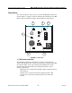
Internal Adjustments and Connections
The controls and connectors found inside the MR-202 and MR-204 are shown
in the following figure and described by the following text. The jumpers can be
accessed without completely removing the panel from its wall box by
removing the top two screws and loosening the bottom two screws a few
turns. The panel can then be leaned out from the wall. The jumpers will be
accessible as shown in the lower view of Figure 2 on page 5.
FIGURE 2: Internal Adjustments and Connections
View from top
of MR-202
Front Panel
P3 Must be
installed if
no option
P1 Must be
installed if
no option
JB1
JB2
7
89