
User manual


MR-202/MR-204 Two- and Four-Channel Headset Stations Clear-Com Intercom Systems
Rev. B
6
© Clear-Com Intercom Systems 2000
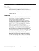
7—Option Jumpers
Two option jumpers, JB1 and JB2, are provided. They should be configured
when the system is set up, but shouldn’t need to be changed during normal
operation.
Note:
The default position of the jumpers is in the OPEN (only one pin
connected) position. The function of each jumper is as follows:
JB1—Long Line
If a long cable run is unavoidable and approaches 1,000 ft. or more, set the
Long Line option jumper to the CLOSED (both pins connected) position. The
ability to set a sidetone null depends upon properly setting this jumper.
JB2—Latch Disable
Setting the Latch Disable jumper to the CLOSED (both pins connected)
position will disable the latching function of the Talk button. In this mode, the
Talk button must be held in continuously while the operator is talking.
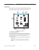
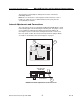
8—Intercom Line Connection
The MR-202 contains a five-terminal, plug-on connector for intercom line
connection. The MR-204 contains a seven-terminal, plug-on connector for
intercom line connection. This connector is intended to be unplugged from the
circuit board when connecting the intercom line(s), and then plugged back on
when the wiring is completed. If less than the maximum number of intercom
lines are to be connected to the intercom connector, link unused intercom
inputs to a connected input with jumper wires. The connections for each pin
are visible on the circuit board when the connector is unplugged. The pinout
of this connector is as follows:
• Pin 1—(NC)
• Pin 2—Channel A Audio
• Pin 3—Channel B Audio
• Pin 4—Power (+30 VDC)
• Pin 5—Ground (Shield)
• Pin 6—Channel C Audio (MR-204 only)
• Pin 7—Channel D Audio (MR-204 only).