R-Series Data Center Products User’s Guide Rev G
Technical Support Please refer to our support website for technical updates, additional warranty information and documentation, and software revisions: Web: http://www.clearcube.com/support/ Email: support@clearcube.com Phone: (512) 652-3400 or call toll free (866) 652-3400 (United States) ClearCube Technology Corporate Headquarters Mailing and Shipping Address: ClearCube Technology, Inc. 3700 W Parmer Lane Austin, TX 78727 Email: info@clearcube.
Contents How to Use this Guide . . . . . . . . . . . . . . . . . . . . . . . . . . . . . . . . . . . . . . . . . . . . . . . . . . . . . . . ix FCC Warning . . . . . . . . . . . . . . . . . . . . . . . . . . . . . . . . . . . . . . . . . . . . . . . . . . . . . . . . . . . . . . ix California Proposition 65 Statement . . . . . . . . . . . . . . . . . . . . . . . . . . . . . . . . . . . . . . . . . . . . ix WEEE Information. . . . . . . . . . . . . . . . . . . . . . . . . . . . . . . . . . . . . . . . . . .
Chapter 3. Chassis and Blade Installation. . . . . . . . . . . . . . . . . . . . . . . . . . . . . . . . . 19 Tools for Installation. . . . . . . . . . . . . . . . . . . . . . . . . . . . . . . . . . . . . . . . . . . . . . . . . . . . . . . . 19 Shipment Components . . . . . . . . . . . . . . . . . . . . . . . . . . . . . . . . . . . . . . . . . . . . . . . . . . . . . . 19 Chassis Installation . . . . . . . . . . . . . . . . . . . . . . . . . . . . . . . . . . . . . . . . . . . . . . . . . . . . . . . . .
R4300 Chassis Upgrade Kit Installation . . . . . . . . . . . . . . . . . . . . . . . . . . . . . . . . . . . . . . . . .55 Fiber Transceiver and Cable Requirements . . . . . . . . . . . . . . . . . . . . . . . . . . . . . . . . . . . . . . .57 PC Blade Installation . . . . . . . . . . . . . . . . . . . . . . . . . . . . . . . . . . . . . . . . . . . . . . . . . . . . . . . .58 Unpacking the PC Blades . . . . . . . . . . . . . . . . . . . . . . . . . . . . . . . . . . . . . . . . . . . . . . . . .
R3040S Hard Disk Tray, Drive Layout, and SATA Headers on Motherboard. . . . . 85 Replacing an R3040S Hard Disk . . . . . . . . . . . . . . . . . . . . . . . . . . . . . . . . . . . . . . . . 85 R3080D Hard Disk . . . . . . . . . . . . . . . . . . . . . . . . . . . . . . . . . . . . . . . . . . . . . . . . . . . . . . 88 R1350 Hard Disk . . . . . . . . . . . . . . . . . . . . . . . . . . . . . . . . . . . . . . . . . . . . . . . . . . . . . . . 89 Replacing CPU Fans . . . . . . . . . . . . . . . . . . . . .
Return Merchandise Authorization (RMA) . . . . . . . . . . . . . . . . . . . . . . . . . . . . . . . . . . . . . .118 Fuse and Power Cord Replacement . . . . . . . . . . . . . . . . . . . . . . . . . . . . . . . . . . . . . . . . . . . .118 Appendix D. Warranty. . . . . . . . . . . . . . . . . . . . . . . . . . . . . . . . . . . . . . . . . . . . . . . . 121 Appendix E. Waste Electrical and Electronic Equipment Directive (WEEE) . . . . 125 WEEE Information. . . . . . . . . . . . . . . . . . . . . . . . . .
viii • Contents R-Series Data Center Products User’s Guide
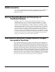
Introduction How to Use this Guide Thank you for purchasing your quality ClearCube products. The ClearCube Architecture was developed to bring you unprecedented levels of manageability, security, reliability, and space savings. The ease of use of ClearCube’s products will make installation straightforward. This manual provides all the product and installation information needed to set up and run ClearCube Technology’s R-Series architecture for managed desktop environments.
WEEE Information See “Appendix E.Waste Electrical and Electronic Equipment Directive (WEEE)” on page 125 for detailed information about the Waste Electrical and Electronic Equipment Directive.
Warnung zum medizinischen oder klinischen Einsatz von ClearCube-Produkten ClearCube-Produkte sind nicht für Komponenten oder zum Testen geeignet, bei denen eine Betriebssicherheit gewährleistet sein muss, die bei der Verwendung mit oder im Zusammenhang mit chirurgischen Implantaten oder als kritische Komponenten in jeglicher Art von Lebenserhaltungssystemen einher geht, bei denen ein Funktionsausfall eine ernstzunehmende Verletzung eines Menschen zur Folge haben kann.
Below are the graphical symbols that are used on ClearCube Technology, Inc. Products and their meaning. Refer to Manual Used on the equipment’s rating label to direct the operator or service person to the manual for additional information. Shock Hazard This symbol indicates the presence of electric shock hazards. Enclosures marked with these symbols should only be opened by qualified service personnel. Refer to the manual for additional information.
WARNING: A Warning notice in this manual indicates that catastrophic equipment damage, or serious injury including death may result if proper procedures are not followed. Safety Guidelines Before undertaking any troubleshooting or maintenance procedure, read carefully all WARNING and CAUTION notices. This equipment contains voltage hazardous to human life and is capable of inflicting personal injury.
• • • • • Live Circuits – Operating personnel and service personnel must not remove protective covers when operating the ClearCube chassis. Adjustments and service to internal components must be undertaken by qualified service technicians. During any service of this product other than replacing a PC blade or externally accessible modules on the chassis, the main connector to the premise wiring must be disconnected. Dangerous voltages may be present under certain conditions. Use extreme caution.
signification de ces symboles. Les symboles graphiques et leur signification, ci-dessous, sont utilisés sur les produits de ClearCube Technology, Inc. Se reporter au manuel Ce symbole sur l'étiquette d'identification de l'appareil est destiné à attirer l'attention de l'utilisateur ou du technicien de maintenance sur les renseignements supplémentaires portés sur le manuel. Risque de choc Ce symbole indique la présence des risques de décharge électrique.
PRÉCAUTION : une note de précaution indique que l'appareil peut être endommagé ou que l'utilisateur risque d'être légèrement blessé si les procédures correctes ne sont pas suivies. ATTENTION : ce message indique que l'appareil pourrait être sérieusement endommagé ou que de graves blessures ou la mort peuvent résulter au cas où les procédures correctes ne seraient pas suivies.
• • • • • • requis. Pour le remplacement des cordons d'alimentation, consulter Annexe C – Support Technique (Appendix C – Technical Support). Système d'alimentation IT – L'équipement ClearCube a été évalué et déclaré compatible avec les systèmes de distribution d'alimentation IT d'une tension composée d'un réseau triphasé ne devant pas dépasser 240 V.
Symbole – Deutsche Symbole auf den Geräten geben dem Benutzer und dem Wartungspersonal bestimmte wichtige Informationen. Es ist wichtig, die beabsichtigte Bedeutung dieser Symbole zu verstehen. Die nachstehend angezeigten Symbole verweisen auf die durch ClearCube Technology, Inc. verwendeten Symbole und ihre Bedeutungen. Nähere Angaben im Handbuch Wird auf dem Gerätebewertungsetikett verwendet, um den Benutzer oder das Wartungspersonal auf weitere Informationen im Handbuch aufmerksam zu machen.
VORSICHT: Ein Vorsichtshinweis weist darauf hin, das Geräteschäden oder geringe Verletzungen bei unsachgemäßer Bedienung erfolgen können. WARNUNG: Ein Warnhinweis weist darauf hin, das vollständige Geräteschäden oder schwere Verletzungen einschließlich des Todes bei unsachgemäßer Bedienung erfolgen können. Sicherheitsrichtlinien Vor der Durchführung von Fehlerbehebungs- oder Wartungsarbeiten sollten Sie alle WARNUNGS- und VORSICHTSHINWEISE genau durchlesen.
von Netzkabeln finden Sie im Anhang C – Technischer Support (Appendix C – Technical Support). • • • • • • IT-Leistungssysteme – ClearCube-Geräte wurden ausgewertet und kompatibel zu IT-Leistungsverteilungssystemen mit einer Phasenspannung von nicht mehr als 240 V befunden. Angeschlossene Stromkreise – Betriebs- und Wartungspersonal sollten die Schutzabdeckungen nicht entfernen, wenn der ClearCube Chassis in Betrieb ist.
Símbolos – Español Los símbolos se usan en el aparato para comunicar información específica a el operador y a la persona de servicio. Es importante entender la intención del significado de estos símbolos. Abajo se muestran los símbolos gráficos que se usan en los productos ClearCube Technology, Inc., así como su significado. Consultar el manual Se usa en la etiqueta de especificaciones del aparato para dirigir al operador o persona de servicio a que consulte el manual para información adicional.
Estos mismos símbolos se usan en este documento cuando es apropiado para indicar situaciones que ameritan revisar este u otro manual, o que pudieran resultar en daño al aparato o lesión física. PRECAUCIÓN: Un aviso de Precaución indica que puede ocurrir daño al aparato o lesiones menores si no se siguen los procedimientos adecuados. ADVERTENCIA: Un aviso de Advertencia indica que puede ocurrir daño fatal al aparato, o lesiones serias incluyendo la muerte si no se siguen los procedimientos adecuados.
• Adaptadores de alimentación – ClearCube o distribuidores de ClearCube proveen de adaptadores de alimentación que están específicamente diseñados para usarse con la pieza del aparato en particular y están aprobados para su uso por las autoridades en jurisdicción en el país donde el aparato se pone en servicio. Por favor consulte las secciones de instalación de este manual para los requerimientos específicos de los cables de alimentación.
Los dispositivos marcados cumplen con el código federal FDA 21 CFR 1040 por notificación 50 y/o el acta canadiense REDR C1370 para dispositivos con emisión de radiación.
Chapter 1. ClearCube Architecture and Product Overview The ClearCube architecture delivers Intel®-based PC functionality to the desktop from a secure, centralized location. This architecture provides significant increases in manageability and security while providing mission-critical reliability, performance, and uptime improvements with lowered costs.
R-Series PC Blade The ClearCube PC blade is a dedicated computer that delivers full PC functionality (including USB) to the desktop from a centralized location. Each R-series PC blade contains all the industry-standard components of a desktop PC: processor, memory, hard disk, video support, and Ethernet. You can easily connect peripherals to the PC blade through USB ports on the User Port that is connected to the blade over a network. Additionally, a single USB port is located on the front of the blade.
A display area at the front of each blade provides active status indicators. The four LEDs on the front panel of the blade are described in Table 1 on this page and shown in Figure 2 on page 4. Table 1 Blade LED Functions LED Color Description Green Blade is powered on. Off Blade is powered off. Power C/Port Green C/Port is connected, and link is good. Red C/Port is not connected, or link is bad. NOTE: The C/Port LED does not provide any information about PCoIP link status.
Front Panel Display outside of Chassis Power Indicator 138 C/Port Link Indicator‡ Hard Disk Activity Indicator Network Activity Indicator Reset Button Power Button Front Panel Display inside Chassis (Including Labels on Chassis Door) 138 Chassis Slot Designation (1 to 8) USB Port Figure 2 ClearCube R-Series Blade Front Panel Display outside of Chassis and inside Chassis (the Chassis Door Provides LED and Button Labels) ‡ The C/Port LED is only applicable if a C/Port is connected to a blade.
R-Series Chassis The ClearCube R-series chassis is a centralized chassis that houses up to eight single-slot PC blades and up to four dual-slot PC blades. A standard 42U 19-inch rack can hold as many as 14 chassis, for a total of 112 single-slot PC blades, 56 dual-slot blades, or a combination of both. Each chassis is a self-contained unit providing all of the Ethernet connections, C/Port connections, airflow management, and power connections for PC blades.
Figure 4 R4300 Chassis Rear View C/Port The C/Port, shown in the following figure, is a desktop unit to which a user’s standard peripherals are connected. The C/Port supports a 200-meter (660-foot) connection distance from the blade and has two USB 1.1 ports, PS/2 mouse and keyboard ports, speaker and microphone ports, and SVGA video output port. Other C/Port options such as the Multi-Video Expander (MVX) are also available from ClearCube.
Multi-Video Solution The ClearCube multi-video solution provides a revolutionary way to multi-task and process information. While the C/Port provides all the peripheral and USB connections, the multiplexed video signal can be passed through to the Multi-Video Expander (MVX) via a noise-limiting VGA connector cable. Shown in Figure 6, the MVX is physically the same size as the standard C/Port and can be stacked on top of a C/Port.
Fiber Transceiver The Fiber Transceiver, shown in Figure 7, is a 1U high, rack-mounted device designed to work specifically with the ClearCube architecture. Figure 7 ClearCube F6150-160 Fiber Transceiver The F6150-160 Fiber Transceiver converts signals sent between C740 Fiber C/Ports (shown below) and ClearCube blades. A single 16-port Transceiver supports two R4300 chassis or 16 PC blades. Each blade in a chassis is connected to the transceiver by an Ethernet cable (≤ 10 meters).
Zero Clients and Thin Clients ClearCube PCoIP® zero clients and thin clients connect to PC blades over a standard Ethernet network. The Clients deliver video and peripheral signals to a local user from a centralized PC blade, just like the C/Port. However, the key difference is that the client connection (depending on the model) uses PCoIP protocol, Ethernet protocol, or both, allowing it to work over standard switched networks.
10 • ClearCube Architecture and Product Overview R-Series Data Center Products User’s Guide
Chapter 2. Network Planning and Site Preparation Rack and Cabinet Requirements Before installing the components of the ClearCube Architecture it is very important to properly prepare the site where you will install the chassis and PC blades. This chapter provides important information on how to plan for installation. Figure 10 Standard 19-Inch Rack and Standard 19-Inch Cabinet Figure 10 shows two frequently-used structures for holding ClearCube chassis.
Fully enclosed electrical cabinets are the preferred option for mounting your ClearCube chassis. When using cabinets, make sure that both front and back panels and doors are vented to provide sufficient airflow for intake and exhaust. If you plan to use a cabinet enclosure, ensure that you have at least 34 inches (86cm) of interior depth measured from the front of the unit, to accommodate the cabling that exits from the back of the chassis.
Power and Cooling Requirements The ClearCube Support site provides ClearCube Power and Cooling Requirements Spreadsheets that you can use to determine power and cooling requirements for ClearCube blade and chassis deployments.
If you are putting multiple chassis assemblies on a single power circuit, ensure that the circuit can safely handle the combined maximum currents of all chassis. CAUTION: Make sure your power strips, power grid, and circuit breakers can safely provide the required current. Ensure that any extension cords used meet local safety regulations and local fire codes. When installing uninterruptible power supplies (UPS), consult your UPS specifications for proper sizing.
Each fully loaded chassis requires eight C/Port cables with RJ-45 connectors for connections to C/Ports at the desktop and eight network cables for blade connections to the Ethernet network hub or switch. Additionally, short color-coded C/Port cables (Green for RS485, Red for Sparing, and Yellow for Admin Port) are provided to configure and daisy-chain your BackPacks. You need eight network cables per chassis to connect the blades to your network switch.
User Desktops with Fiber C/Ports Data Center Chassis Admin C/Port and Terminal Ethernet Cables Network Switch (Alternatively, Deployments Can Omit the Network Switch and Directly Connect the Chassis to the Fiber Transceiver) Fiber Cables F6150 Fiber Transceiver Figure 12 ClearCube Digital Fiber C/Port Architecture Cabling Diagram User Desktops with Zero Clients and Thin Clients Data Center Chassis Admin C/Port and Terminal Ethernet Cables Network Switch Figure 13 ClearCube Client Architecture Ca
The following figure shows cabling between PCoIP zero clients and blades with PCoIP host cards. For more information about the cabling, shown in the following figure, see Table 7, “R4300 Network Module Features: Models 4362 (EP2) and 4363 (EP6),” on page 32.
18 • Network Planning and Site Preparation R-Series Data Center Products User’s Guide
Chapter 3. Chassis and Blade Installation The following instructions are intended for use by IT technicians familiar with computer systems at the hardware configuration level.
• Monitors and keyboards – Monitors are normally shipped in their own cartons. Keyboards, if not included with user ports, may be bulk-packaged. Shipping cartons and packing materials should be retained until your ClearCube installation has been completed and tested. Chassis Installation Unpacking the Chassis Open the chassis box, remove the packing material, and check the chassis for any visible damage. Contact the carrier for an immediate on-site inspection if damage is found.
Begin installing your chassis assemblies at the bottom of the rack or cabinet. This provides support for each chassis before it is securely mounted, and greatly simplifies getting the chassis square and level in the rack. Standard Chassis Mounting Hardware To install a chassis using the standard Chassis Accessory Kit, do the following: 1. When installing into a cabinet enclosure, loosely attach the back adjustable mounting brackets to the chassis with 5 screws on each side. 2.
Figure 15 Side View of Chassis Centered in a Two-Post Rack 6. Attach the AC power cord(s) packaged and supplied with the chassis and route it to the back panel power connector(s) and then to a surge-protected power source such as an uninterruptible power supply (UPS) or power strip.
To install a chassis using the CRM kit, do the following: Front Rack Ears Locking Latch Main Bracket Spring Slider Slider (Back) Rack Ears Finger Handle Flanges Figure 16 Rack Bracket for CRM Kit 1. Unscrew the thumbscrew holding each pair of chassis and rack brackets together, and slide the brackets apart. 2. Mount the chassis bracket to the chassis with 4 flathead screws. Repeat on the other side. NOTE The chassis and rack brackets are interchangeable side-for-side. 3.
4. Pull the rack bracket forward and insert the front rack ears on the back bracket into holes on the front side of the front post. Push forward on the ears until the latch snaps and locks into place. Ensure the front ears are placed into the corresponding holes as the back ears, so that the rack bracket is level. To remove, pull the finger tab inward with your finger and slide the ears forward. 5. Repeat steps 2 and 3 with the other chassis bracket on the opposite side of the rack, in mirrored orientation.
The standard 10-amp power cords are acceptable for use with the Fiber Transceiver. See “Safety Guidelines” on page xiii for more information. Make sure your power strips, power grid, and circuit breakers can safely provide the required current. Ensure that any extension cords used meet local safety regulations and fire codes. When specifying uninterruptible power supplies (UPS) be sure to include the Fiber Transceiver peak current draws in your calculations to ensure the UPS has adequate capacity.
The R4300 accepts the modules as shown in the positions in Figure 18. Chassis AC Backplane Power Supply Modules Fan Pack Dual A/C Input Module Connect Bay Module Network Module Management Module Figure 18 R4300 Exploded View R4300 Modules Install R4300 modules by sliding them into their respective bays and seating the connector. Connect, Management, and Network modules are hot-swappable, and can be replaced without affecting any existing switching configurations within the chassis.
The first three characters of a module’s serial number, shown on the back apron and visible when the module is installed in its bay, are the same as the module’s abbreviation. For example, the serial number XCM12345 identifies a 8 x 8 Connect Module.
Connect Module Management Module Network Module Figure 21 R4300 Modules The Connect Module (shown on the left in Figure 20) provides connectors for C/Ports, USB ports, and sparing. On the right, the Network Module (either Model R4362 [EP6] or Model R4363 [EP2]) provides Ethernet connections. In the center, the Remote Management Module provides network and daisy-chain control connections, chassis health indicators, and fan speed control.
ADMIN OUT Yellow RJ45 connection that links to the ADMIN IN connection of the next chassis in the Admin daisy chain. On the end of the Admin daisy chain opposite the Admin C/Port, this connector is not used. SPARE IN Red RJ45 connection that links a Spare blade into the Spare daisy chain, or passes the Spare connection to another chassis by connecting to that chassis’ SPARE OUT port. As many as 14 chassis per Control Chain can be connected on one Spare daisy chain.
• C/Port connection status — Green = good digital link to blade — Red = bad digital link to blade — Off = no blade • STATUS USB connection status — Green = USB available — Red = USB not available — Off = no blade Blue • Network connection status — Green = good network connection — Off = no network connection, or no blade C/PORTS USB Blue Blue Blue LED that, when lit, indicates that the Status LEDs above the Management Bay module are displaying status for the C/Port connections.
Table 6 R4300 Remote Management Module Features RMM Reset Default Switch Ethernet LEDs RMM Hardware Reset Switch Ethernet LEDs LINK RMM Status LEDs ACTIVITY Control Chain Connections Module Mode Switch Ethernet Connection RMM Status LEDs Fan Mode Switch RMM MODE DHCP DC POWER HEALTH Connectors Label Color Code CONTROL IN Green RJ45 connection that receives control and management signals from the previous chassis in the Control Chain via RS-485.
Bi-color LED indicates IP address assignment mode DHCP — • • Green = DHCP Off = fixed IP address Bi-color LED indicates power supply status DC POWER — • • • Green = 2 supplies good Red = 1 supply bad Off = no power or RMM not seated properly Bi-color LED indicates system health HEALTH — • • • • Green = good Amber = RMM firmware update in progress Red = bad Off = no power or RMM not seated properly See the Sentral Administrator’s Guide for more information on RMM Status indicators Bi-color LEDs t
The PSUs are factory-installed, field-replaceable units. Each PSU has a green LED visible through the fan pack that indicates its powered-on status. If one of the PSUs fails, the DC POWER status LED on the RMM turns red to indicate a failure, and the green LED on the failed power supply turns red. The DIM allows providing redundant power inputs. For best reliability, attach a power cord to both receptacles, and plug the cords into separate power sources.
Primary, and RMMs on the chain all serve as Tertiary controllers. A Control Chain can contain as many as 14 chassis. • Admin Daisy Chain – The link between an Admin C/Port and the chassis served by that Admin C/Port. An Admin Daisy Chain can connect from 1 to 14 chassis within a single Control Chain, depending on the model of the connected C/Port. The Admin Daisy Chain uses the same ClearCube proprietary data link that connects blades to C/Ports.
blades (configured by daisy-chaining the spare connections). Figure 23 on page 35 shows these sparing scenarios as examples. NOTE Sparing is a switching function of the R4300 chassis. If no spare blade is connected to the Spare Daisy Chain, or if the Spare blade is completely powered down, the spare switch action will succeed but the user will not be connected to a usable blade.
than one switch and/or subnet to better protect against network-related failures. As many as 14 RMMs per Control Chain (all of them) can be connected to the network to provide failover capability. In practice, three is probably enough. NOTE Do not use an Ethernet port on the chassis for this connection. 4. Skip this step if installing only other clients, or if using a chassis with an ACM. Connect eight C/Port cables from the XCM ports marked C/PORT to the patch panel going to your desktops.
We suggest routing the cables down the sides of the rack to the back panel, with the network cables on one side and the desktop cables on the other.
control. One or more RMMs need to be connected to Ethernet to allow auto-negotiation and control failover. Figure 25 shows an example of this.
Admin C/Port and Terminal #1 Primary Chassis with E-net Control Link Spare Configuration Cable To Network Spare Daisy Chain Spare Configuration Cable Primary Chassis with E-net Control Link To Network Admin C/Port and Terminal Spare Daisy Chain #1 Admin Daisy Chain #1 Admin Daisy Chain Control Chain Control Chain Spare Configuration Cable Admin C/Port and Terminal #2 Spare Daisy Chain #2 Admin Daisy Chain #2 Spare Configuration Cable Spare Daisy Chain #3 Control Chain with Single Daisy Chains
R3040S Cabling Because R3040S blades use two slots in a chassis, the rear of a ClearCube chassis (shown below) provides up to four Gigabit Ethernet ports (two primary ports and two secondary ports) for each blade, depending on video card configuration.
blade and client are on the same subnet or, if they are on different subnets, that the devices can communicate. • Connect to a network that reserved for PCoIP traffic—To isolate PCoIP traffic on a specific network, connect one end of an Ethernet cable to the chassis port reserved for PCoIP communication (as noted above), and then connect the other end of the cable to a network that you specify for PCoIP traffic.
MAC Address Label on R-Series Blades A label on the exterior of each R-series blade specifies the Media Access Control address (MAC address) of each network adapter. The following sections illustrate the location of the MAC address label and additional labels. R3040S Labels The following figure shows the label on the blade exterior that specifies each network adapter MAC address and additional labels.
R1350 Labels The following figure shows the label on the blade exterior that specifies each network adapter MAC address and additional labels.
How OS Network Connections Are Mapped to NICs on Chassis Backpack After you insert a blade in a chassis, your Windows operating system shows 2 network connections in the Network Connections window (click Start > Control Panel and then double-click Network Connections to display connections). The following table shows how each network connection that your OS displays is mapped to the Ethernet ports (Primary & Secondary) on the rear of the chassis (shown Figure 27 on page 40).
3. Telnet into the Primary RMM and verify your RMM firmware version. a. Telnet into the Primary RMM by entering the following at a command prompt: telnet RMMIPAddress where RMMIPAddress is the IP address for the RMM. b. Log in to the RMM, and enter the following command: ver If the RMM is version 5.x or higher, continue with this procedure. If the RMM is version 4.x or lower, contact ClearCube Technical Support. 4.
2. Unzip the update package and read the enclosed Technical Bulletin (a PDF file) to learn any special considerations for the package. 3. Copy the package to a directory visible to the Sentral Console. 4. From the Functional menu, select Management > Chassis. 5. In the Tasks menu, click Update Firmware. 6. Select the primary RMM from the Primary Execution Pane. 7. In the Tasks menu, click on Select for Update. 8.
RMMs can only be installed in R4300 chassis. A BSBP without an RMC installed can perform C/Port Switching, Admin Switching, and Sparing under the control of an RMC or an RMM. Each RMM in an R4300 series chassis provides an Ethernet connection, allowing it to control a chain of as many as 14 chassis. If an RMM is not connected to Ethernet, it does not auto-negotiate, and provides control and monitoring only for the chassis in which it is installed.
• Do not use Mixed Mode (connecting a mix of R4300s, BSBPs, and/or DCBPs) for connecting your Control Chain. • Use an RMC to manage only BSBP- and DCBP-equipped chassis. • Configure RMCs using Telnet. • Use an RMM to manage new R4300 chassis, and BSBP- and DCBP-equipped chassis that do not contain an RMC. • Configure RMMs using Sentral.
The following figure shows the list of configuration parameters. Figure 29 RMM Parameters via Telnet 3. Enter the command to change a parameter in the format: cfg ParameterName Value where ParameterName is the parameter and Value is its desired new value. 4. When finished changing parameters, type exit to close the Telnet window. Resetting the RMM Settings to the Factory Defaults In normal use, the RMM is configured using Sentral.
Table 10 R4300 RMM Default Configuration Settings (Continued) Field Name Function Setting Options Default Setting RMMGateway RMM Gateway Ignored if IP Mode = DHCP 192.168.1.
Table 10 R4300 RMM Default Configuration Settings (Continued) Field Name Function Setting Options Default Setting Timestamp Timestamp Seconds since Jan. 1, 1970 Set from real-time clock RMMPoll RMM Poll Time period for RMM “heartbeat” 5 minutes SMIP2 Sentral Secondary Console IP Address xxx.xxx.xxx.xxx 192.168.1.252 NOTE For failover between Primary and Secondary RMMs to occur successfully, the RMMs must have the same password, and Alerting and Logging must be activated.
• Configure the Blade Switching BackPack for Various Modes: Configuration of your Blade Switching BackPack depends on that modes of operation you will use. All modes can be used together, or individual modes can be used alone. • Spare Switching Configuration: Multiple spare PC blades can be configured per chassis. At the other extreme, one spare can be made available to support 14 chassis.
each RMC with a different IP address. This allows you to log in to each group of chassis independently. NOTE Every primary R4200 chassis with an RMC installed is shipped with the same default network settings. If you are using multiple Chassis groups, you must configure new IP addresses per the instructions below to avoid a conflict. Default RMC Settings: IP Address: Gateway: Network: Netmask: 192.168.1.251 192.168.1.1 192.168.1.0 255.255.255.
The result should be: >1 new ip: 4. Type in the desired new IP address. For example: >1 new ip: 192.168.1.100 (your desired IP address) The result should be: RMC Configuration 1. IP address: 192.168.1.100 2. Gateway: 192.168.1.1 3. Network: 192.168.1.0 4. Netmask: 255.255.255.0 5. Password: clearcube 6. Exit NOTE The IP address should be the new one you typed in. 5. Change the Gateway, Network, and Netmask settings, using the same procedure. For Gateway, use your network’s default gateway setting.
Connect the CONTROL IN port to your regular network using a standard network cable. Make sure not to use the cross-over cable you were just using. Test the connection to the RMC by pinging its address from any other computer on the network. NOTE It is recommended that you change your password for security reasons. If you are unable to connect to the RMC card across your network, make sure the network connection at the switch for your RMC is able to pass 10Mbps traffic.
6. Remove the 2 Phillips screws retaining the BackPack. 7. Pull the BackPack by the two tabs and remove it from the chassis. 8. Unsnap and remove the black plastic shield from the AC backplane by pulling upwards on it. 9. Remove the 9 hex head screws from the AC backplane. 10. Remove and discard the AC backplane. Figure 30 Exploded View of Upgrade Kit Components 11. Install the new R4300 upgrade parts in the chassis. 12. Place the AC backplane module in the chassis and secure it with 4 hex head screws.
Fiber Transceiver and Cable Requirements See ClearCube F6150 Fiber Transceiver User’s Guide for information about installing and using the fiber transceiver and for information about transceiver power requirements. See http://www.clearcube.com/support/controller/home.php to download the F6150 Fiber Transceiver User’s Guide. The Fiber Transceiver and Fiber C/Port are Laser Class 1 Products. See “Safety Guidelines” on page xiii for additional information.
The fiber optic cables from the output of the Transceiver can be home runs to the individual fiber C/Ports, or they can be patch cables that run to one or more fiber patch panels. The following requirements apply to the ClearCube Fiber Optic Extension System: • The power budget through all the connections between the Transceiver and the Fiber C/Port must be 6 dB or less, including the cable itself. • This system connects PC blades at a maximum distance of 2000 meters over a pair of 50µm or 62.
To install a blade, do the following: NOTE Never force blades into a chassis. Mishandling blades can cause critical hardware failure, data loss, or both. 1. Lower the front bezel on the chassis by depressing the latches on each side. 2. Orient each blade right-side up (LCD panel on the bottom) and then slowly insert the blade into the chassis by lining up the blade edges with both the top and bottom guides in the chassis. 3. Start inserting blades with the left-most slot.
When a blade is inserted into a chassis, it takes approximately 30 seconds for the chassis and its RMM to detect the blade and relay its information to Sentral. Note that the blue LCD panel and the C/Port indicator remain lit, independently of whether the blade is powered on. These indicators run off of chassis power. After the first on/off cycle, you can power the blade back on from the shutdown state by either pushing the power button on the blade or the Reset/Power button on the C/Port.
To connect C/Ports to a dual-slot blade, use only the even-numbered C/Port connectors 2, 4, 6, or 8, relative to those slot pairs. The odd-numbered C/Port connections on the chassis are not connected to dual-slot blades. R3080D Video Options and Ethernet Port Behavior The R3080D provide two Ethernet ports that correspond to the primary and secondary Ethernet jacks on the rear of a chassis. Your graphics card configuration determines the behavior of the blade’s Ethernet ports.
When connecting to an R3040S, use the even-numbered USB ports on the back apron of the R4300. The odd-numbered USB ports on the chassis are not connected to the R3040S. This is the same scheme as with connecting C/Ports to a dual-slot blade. See “Mass Storage Lockout: Disabling Access to USB Mass Storage Devices” on page 71 for information about enabling and disabling USB ports on user ports (zero clients, thin clients, and so on).
two or more DVI-I displays to your PCoIP client. Perform the following steps to disable the default VGA display and enable one or more additional DVI displays. 1. Connect one or more additional DVI displays to your PCoIP client. 2. Right-click an empty area on the desktop. 3. Select ScreenToys from the right-click menu to display the Device Management dialog box. Monitor Menu Display Devices Area 4. From the Monitor menu, select the VGA display.
From the BIOS setup utility you can configure boot sequence, hard disk settings, power-up defaults, power management settings and more. (Note that you can select the first boot device without entering the BIOS setup utility. Follow the on-screen prompts as the blade boots. If you are booting from a USB CD-ROM device, select CDROM (do not select removable device.) ClearCube PC blades uses a lithium coin-cell battery for backing up parameter memory.
MSL Jumper USB Mass Storage devices function normally (default) 3 JP6 USB Mass Storage devices do not function 3 JP1 1 1 CMOS Jumper Normal operation (default) 3 Reset CMOS password on restart 3 1 1 Figure 33 Model R1350 MSL and CMOS Jumper Locations and Settings Clearing All R3080D and 3040S CMOS Settings The R3080D and R3040S motherboards provide a jumper you can use to clear all current CMOS settings. By default, the jumper is on pins 1 and 2 for normal operation.
Perform the following steps to clear all CMOS settings. 1. Power down the blade and remove the blade from the chassis (if the blade is not in an enclosure—for example, for configuration—ensure that power is disconnected). 2. Locate header JP10 on the R3080D (see Figure 34 on page 65) or header JP3 on the R3040S (see Figure 35 on this page). 3. Use needle-nose pliers to move the jumper from the default position (on pins 1 and 2) to the reset/clear position (on pins 2 and 3). 4. Wait five seconds. 5.
ClearCube blade image and from the ClearCube Support Web site before you create a RAID volume, which will remove the drivers from the hard disk. • Determine the RAID configuration to use for the volume you are creating. • Enable RAID in R3040S BIOS and make additional BIOS configurations as described in the following section. • Use Intel Storage Matrix Manager to create RAID volume. • Obtain a USB floppy drive and floppy disk to install the drivers during operating system installation.
10. Press F10 to save your changes and exit Setup. NOTE As discussed in the first step in the following section (“Creating a RAID Volume Using Software RAID”), be prepared to press CTRL+I when prompted after the blade reboots. 11. Select OK and then press Enter to reboot the blade. You can now continue to create the RAID volume using the Intel Matrix Storage Manager, as described in the following section.
3. From the Name field, type a name for the RAID volume you are creating (there is a 16-character maximum and special characters are not allowed). Press Enter after typing the name. 4. Use the arrow keys to scroll through the menu of RAID levels (R3040S supports RAID levels 0, 1, 10, and 5). Select a level and then press Enter. 5. If you are configuring RAID 10, skip this step and continue to step 7. Select Disks is highlighted. Press ENTER to specify disks to add to the volume. 6.
From the Support site, click PC Blades > R3040S > Drivers and then click the link for the operating system you are installing. b. Extract the RAID drivers in the archive file you just downloaded to a 3½-inch floppy disk (see the readme file in the archive for the location of the RAID drivers). c. Extract the remaining drivers to a storage device so you can install them after installing the operating system. 2.
7. Setup displays a screen requesting that you specify the SCSI adapter. Scroll to Intel(R) ICH8R/ICH9R/ICH10R/DO/5 Series/3400 Series SATA RAID Controller (the third entry) and press ENTER. A message is displayed at the bottom of the screen indicating that setup is loading files. 8. Setup displays a screen indicating that is will load support for the controller you specified in the previous step. Press ENTER to continue. Messages are displayed at the bottom of the screen while files are loaded. 9.
MSL is disabled by default. To enable MSL, you must set a jumper on the MSL header: • To enable MSL on an R1350 blade with a V5120 Host card, use MSL header J7 located on the V5120 Host card (shown in Figure 37 on page 72). This configuration does not support MSL through the JP6 header on the motherboard. • For all other configurations, enable MSL using the JP6 header on the motherboard. Additionally, ClearCube Sentral provides software-based MSL to prevent the use of mass storage devices.
– R1350 Using a C/Port MSL header JP6 is located to the left of the DIMM slots, above and to the left of the SATA cable, as shown in the following figure.
R3040S MSL header JP6 is located near the top edge of the motherboard, between the upper set of memory modules and CPU1, as shown in the following figure. Disable 3 2 CPU 0 1 CPU 1 Battery Enable JP6 – JP6 Mass Storage Lockout Header Figure 40 Model R3040S MSL Header Location and Settings (Default Setting Shown on Motherboard; Top Blade Sections Not Shown for Clarity) 3. Use needle-nose pliers to move the jumper.
Flashing the Blade BIOS You can flash (install or re-install) the BIOS for your blade. The BIOS download contains file the following: • BIOS files • BIOS flash utility • Instructions about how to use the flash utility From the ClearCube Support site (http://www.clearcube.com/support/), select your blade form the drop-down list, and then click the BIOS link, located under the blade description. Save and then extract the archive file. Read the enclosed readme.
76 • Chassis and Blade Installation R-Series Data Center Products User’s Guide
Chapter 4. Hardware Upgrade and Replacement Procedures The ClearCube architecture simplifies upgrading PC blades. All blade hardware and software components are classified as one of the following: Customer Replaceable Units (CRUs) Items that customers can replace. Field-Replaceable Units (FRUs) Items that trained service providers and ClearCube Systems Engineers (SEs) can replace, either on site or through an RMA process.
Table 11: Blade Components and CRU/FRU Designation Blade Component R1350 R3040S *FRU R3080D Instructions & CRU CRU See “Replacing and Upgrading Hard Disks” on page 84 CRU FRU & CRU CRU See “Replacing and Upgrading Hard Disks” on page 84 Front LCD Panel CRU CRU CRU See “Replacing a Front LCD Panel” on page 97. Chassis Interposer Card CRU CRU CRU See “Replacing Blade Interposer Cards” on page 102. CPU Fan FRU CRU CRU See “Replacing CPU Fans” on page 89.
CAUTION: All upgrades should be performed by a qualified computer technician. Take proper precautions to avoid damaging electrostatic discharges by working at a grounded computer equipment repair bench. Damage caused by improper upgrade procedures will void your warranty. Disconnect all sources of power before servicing the R4300 chassis. Drivers You can obtain drivers for ClearCube blades from the ClearCube Support site at the following URL: http://www.clearcube.com/support/. To obtain drivers: 1.
Upgrading Memory Only use ClearCube-supplied or ClearCube-approved memory modules. Model R3040S The R3040S provides six DDR3 DIMM sockets in six channels, as shown in Figure 41.
• You must populate CPU 0 socket first to enable and operate the CPU 1 socket. • If the blade uses CPU 0 socket only, a minimum of one 1-GB DDR3 DIMM is required in channel A. If both CPU sockets are populated, a minimum of one 1-GB DDR3 DIMM is required in channel A and in channel D. • If a blade uses two CPUs and there are DIMMs for each CPU, ensure that you populate matching channels. For example, populate channel A and channel D.
Model R3080D The R3080D motherboard supports DDR3 1333 MHz Dual Inline Memory Modules (DIMMs), and provides four 240-pin DDR3 SDRAM DIMM sockets in two channels (channel A and channel B), as shown in the following figure. R3080D Blade Fan and Heatsink DIMM 2 Channel A DIMM 1 DIMM 4 Channel B DIMM 3 Figure 42 Detail of R3080D Memory Channels and Sockets Important Installation Considerations Ensure the following when you are populating DIMMs. • Only use DIMMs supplied by ClearCube.
Installing 3 DIMMs 1. Pull the tabs on either side of the memory socket away from the module to remove the existing DIMMs. 2. Insert DIMMs in sockets 1 and 3 (the black socket of both channels) as described above. 3. Continue by installing the third DIMM in socket 2 or 4 (the blue socket of either channel). Installing 4 DIMMs 1. Pull the tabs on either side of the memory socket away from the module to remove the existing DIMMs. 2.
Replacing and Upgrading Hard Disks The following sections describe how to work with hard disk drives (HDD, or hard disks) in R-series blades. Ensure that you observe the following when working with HDDs: • Hard disk mechanisms are sensitive to mechanical shock, and are most vulnerable when handled as an unmounted unit. Handle them gently, especially when setting them down on a work surface. • Drive cables should be removed by pulling on the connector, not by pulling the cable.
• Small tray (part number G0700056)—contains up to two hard disks. • Large tray (part number G070059)—for multiple configurations: – – – For up to four standard-capacity hard disks For two 300 GB hard disk drives (part number G913040-300) For all hard disk configurations with V5224 PCoIP cards R3040S Hard Disk Tray, Drive Layout, and SATA Headers on Motherboard The following figure shows each R3040S hard disk tray model and details the location of the drives in the tray and the associated cables.
2. Position the blade so the hard disk tray is facing up (the hard disk tray is located on the left side of the blade if you are looking at the front of the blade). 3. Use a a Phillips screw driver to remove the four screws (M3 x 5, flat head screw, part number G7110009) from the hard disk tray, located on the top of the blade. 4. Use the finger holes in the center of the tray to carefully raise tray. Do not pull the tray straight up; rotate the tray on the its long edge as shown in the following figure.
7. Place the new hard disk in the tray. – – Insert hard disks so that the label on the top of the hard disk faces the solid surface of the tray (and you can see the circuitry on the bottom of the hard disk), as shown in the following figure. Ensure that the SATA data and power connectors on each disk are facing away from the front of the blade. An arrow on the underside of the tray points to the front of the blade.
R3080D Hard Disk To replace or upgrade a 2.5-inch hard disk in an R3080D, perform the following steps. Use the correct ClearCube-supplied or ClearCube-approved screws to secure each hard disk to the tray. Screws that are too long can damage hard disks, damage threads in the tray, or both. 1. Power off the blade and remove it from the chassis. Place the blade on a stable surface, such as a desk or bench. Some surfaces on the blade may be hot, especially when the blade has been powered on.
4. Attach the new hard disk. a. Carefully place the new hard disk in the hard disk carrier, ensuring that the: – – Manufacturer label faces the correct direction, as shown above SATA power and data connectors face the end of the carrier that extends past the side walls, as shown above – Carrier and hard disk screw holes are aligned b. Use the four small screws you removed in Step 3 to connect the hard disk to the carrier. 5. Reconnect the carrier to the blade using the three screws you removed in Step 2.
R3040S Fans Each R3040S has two CPU fans: • CPU fan 0, used with CPU 0. The power cable of fan 0 exits from the right side of the fan (a label is on the front of the fan). • CPU fan 1, used with CPU 1. The power cable of fan 1 exits from the left side of the fan (a label is on the front of the fan). Fans are seated in brackets to ensure correct airflow through the blade. NOTE Do not insert screws in fan bracket. No screws are required.
PU 0 C PU C Front of Blade CPU 1 Fan (Cable Exits Left Side of Fan) 1 CPU 1 Fan Header CPU 0 Fan (Cable Exits Right Side of Fan) CPU 0 Fan Header Figure 49 The Location of CPU Fan 0, CPU Fan 1, Power Headers, and the Positioning of Power Cables Perform the following steps to replace a fan. 1. Power off the blade and remove it from the chassis. Place the blade on a stable surface, such as a desk or a bench. 2.
Ensure that you do not loosen memory modules, voltage regulator modules (VRMs), or other components. 6. From the second tier of the blade, unscrew both screws that secure the fan bracket to the blade. Be sure the remember the orientation and position of each fan. Front of Blade Screws Screws Figure 51 CPU Fan Bracket Screws 7. Remove the fan by lifting up the fan bracket and withdraw it from the blade. Make sure that the fan’s power cable does not catch on the blade frame when you remove the fan. 8.
9. Insert the replacement fan in the fan bracket. a. Rest—but do not insert—the new fan in the top of the fan bracket, ensuring that: – – The fan and the bracket are facing forward (a label is on the front of the fan and the front of the bracket has four mounting holes). The power cord is behind the mounting hole. DO NOT INSERT SCREWS IN BRACKET Ensure Fan and Bracket Are Facing Forward Move Power Cord Behind Flanges Before Inserting b.
R3080D Fan The R3080D CPU fan is attached to the CPU heatsink by a bracket. CPU Heatsink Fan Bracket Power Cable NOTE Do not remove the CPU heatsink from the motherboard. Only remove the fan bracket, as shown in the following figure. Perform the following steps to replace the CPU fan. 1. Power off the blade and remove it from the chassis. Place the blade on a stable surface, such as a desk or a bench. 2.
. Heatsink 4. Remove the 4 screws from the bracket and remove the bracket from the fan. 5. Now attach the bracket to the new fan.
An indicator on the bottom of the fan shows the direction of airflow. Airflow Indicator on Bottom of Fan Power Cable Ensure that air flows toward the heatsink and toward the rear of the blade. Heatsink Fan Airflow toward Rear of Blade Place the bracket on the side of the fan where the rotating blades are located. Insert 4 screws you removed in the previous step and tighten. 6. Attach the fan to the heatsink by replacing the two screws you removed in step 3.
Replacing a Front LCD Panel This section describes how to replace the LCD front panel of an R-series blade. 138 Figure 52 The Front LCD Panel The following instructions assume that you have a ClearCube Front LCD Panel kit, ClearCube part number G081001. 1. Power off the blade and remove it from the chassis. Place the blade on a stable surface, such as a desk or a bench. 2.
• R3040S—Insert a screwdriver in the access hole, shown below, to remove the screw. Access Hole for Front LCD Panel Screw Insert Screwdriver Here • R3080D and R1350—Remove the LCD screw, shown in the following figure. LCD Screw Tab LCD Cable 4. Remove the LCD panel. a. From the front of the blade, grasp the LCD panel and cable and lift the panel up. b. Gently rotate the LCD panel forward toward the opposite, interior wall of the blade.
shown below. It might help to push up on the lower tab from the outside of the blade. Ensure That Plastic Tab Is Clear of Blade Frame c. When the panel is clear of the USB connector, pull the panel out of the blade. 5. Remove the LCD by grasping the end of the cable and by grasping the base of the LCD panel. Pull apart to separate. 6. Connect the LCD cable and the replacement front LCD panel. 7.
8. Replace the LCD panel screw, ensuring that the plastic LCD panel flange is on top of the metal blade frame flange, and that the holes are aligned. Do not overtighten or you can break the plastic LCD flange. Ensure That Plastic Flange is on Top of Metal Flange and Holes are Aligned Your front LCD panel replacement is now complete. Replacing the CMOS Memory Battery ClearCube blades use a lithium coin cell to maintain CMOS settings.
• R3040S—CMOS battery is located near the rear edge of the blade, below the J4 header and the JP3 jumper. Side View Rear View Release Tab Battery Battery Release Tab Graphics Card Interposers Battery Holder • R3080D—CMOS battery is located near the center of the blade, adjacent to the processor and beneath the video card. Ensure that you remove any video card that is installed. The following figure shows a blade with the video card removed.
3. There is a release tab at the top of the battery holder that releases the battery when you push the tab away from the battery. Use a non-conductive tool (such as a plastic writing pen) to push the release tab and remove the battery with your fingers. The R1350 battery holder does not have a release tab; use your finger to remove the battery. 4. Allow at least 30 seconds for the CMOS memory to be lost before inserting a new battery. NOTE Observe battery polarity. 5. Replace the blade in the chassis. 6.
2. Ensure that you are working with the shorter of the two interposers, contained in the black, plastic shroud. 3. Unscrew and remove both screws securing the interposer to the blade. Screws 4. Use your finger to gently lift the right side of the shroud and remove it by sliding it off the interposer to the right. 5. Remove the interposer: a. Using your right hand, place your thumb on the edge of the blade frame, just to the right of the interposer. b.
a. Hold the green interposer so the text and labels on the top face up, and hold the shroud so that the CLEARCUBE logo is facing up. b. Hold the shroud above the interposer and slide the gold fingers on the left edge of the interposer though the slot on the left edge of the shroud. Shroud Interposer c. Align the holes of both pieces, and make sure that the pins on the top of the interposer rest in the recesses on the underside of the shroud.
section, “R3040S Interposer Cards” on page 102, to remove an R3080D or an R1350 interposer. Replacing R4300 Management, Connect and Network Modules R4300 Management, Connect, and Network Modules are hot-swappable. To replace a module, do the following: 1. Label all cables attached to the module. 2. Remove the cables. 3. Press down on the two green levers on each side of the module. NOTE Management modules have only one lever. 4. Pull the module from its bay.
5. Slowly insert the new fan pack to ensure proper seating of the connector. 6. Replace the screws to secure the fan pack. 7. Replace the power cords and then power on the blades. Figure 54 R4300 Fan Pack Attachment Points Replacing an R4300 Power Supply Unit (PSU) To replace a PSU in the R4300 chassis, do the following: Use caution when hot-swapping R4300 PSUs and Fan Packs: be sure to follow the instructions below. 1.
Chapter 5. Troubleshooting If you have any problems with your system, please check the following items prior to calling for support. PCoIP Issues PCoIP Host on Different Subnet Than PCoIP Client Is Unable to Wake Up from Various Power States This issue is restricted to R3040S blades that contain V5120, V5220, and V5240 PCoIP host cards. When a PCoIP host system is shut down (S5) or is in hibernate (S4), the PCoIP host transitions to receive a Wake-on-Lan (WOL) packet.
Power Issues No power to PC blade • • • Check the power button on the front of the PC blade. Verify that the power circuit to the chassis is operational. Check all power strips, UPS, and extension cords to make sure they are in working order. No video or link lights at desktops and no power to blades • R4300: Have a qualified service technician check the fuse. CAUTION: DOUBLE POLE/NEUTRAL FUSING The DIM employs fuses in both the neutral and hot lines.
Fiber Optic Troubleshooting No video and/or digital link present • • • Check all the C/Port and fiber optic cables and their associated jacks for signs of damage or wear. Replace any suspicious cables with new, commercially manufactured cables and test the remaining cables with a quality tester. Non-commercial cables are frequently the culprits when equipment fails to work properly. For this reason, ClearCube strongly discourages the use of Non-commercial cables.
110 • Troubleshooting R-Series Data Center Products User’s Guide
Appendix A. Specifications R-Series Blades Table 1 PC Blade Specifications R1350 • Core2 Duo or Intel Pentium 4 with • Hyper Threading LGA775 socket Intel® Xeon® processor 5500 series (Nehalem microarchitecture) • Intel 945G with 1066 MHz front-side bus • Intel 5520 chipset w/ 6.
BIOS Dimensions • • Phoenix® BIOS • Supports PXE, Secure Agent, Multiprobe, PnP, Phoenix Phlash & • Multikey • • 4.7” (H) x 23.5” (L) x 1.9” (W) Weight: 6 lbs. Environmental • Stationary office, 0–35° C AMI® BIOS Supports PXE • • AMI BIOS Supports PXE • • 4.7” (H) x 23.5” (L) x 4.7” (W) Weight: 10-13 lbs. depending on configuration • • Size: 4.7” (H) x 23.5” (D) x 1.
Fiber Signal Loss • Maximum signal attenuation through all fiber runs, patch panels and connectors must meet the following specification: 50/62.5 micron fiber: ≤4.5 dB Max. Jumper Length • R4300 to Transceiver jumper max. length = 100 meters (333 feet) Rack Height • 1U (1.
114 • Appendix A.
Appendix B. Regulatory Compliance The products described in this document meet the following: • • • • Electromagnetic Compatibility (EMC) Various safety compliance standards CE compliance Various environmental standards, including RoHS and REACH See http://www.clearcube.com/support/ for regulatory and environmental certifications for all ClearCube Technology, Inc. products. R-Series Data Center Products User’s Guide Appendix B.
116 • Appendix B.
Appendix C. Technical Support Contact Information In the event any problems arise with your ClearCube hardware or software, we recommend that you first check the support Web site for any relevant technical bulletins and updates for your specific product(s) before calling your authorized reseller or the ClearCube Technical Support Department.
Return Merchandise Authorization (RMA) ClearCube’s policy for products under warranty is to ship replacement parts to the customer within 24-48 hours after the replacement has been approved by the ClearCube Tech Support department. If an issue arises that may require a warranty replacement part, the customer should places a telephone call to Tech Support (see numbers above), use the RMA form on the CCT Support Web site (http://www.clearcube.
with the Fiber Transceiver. Refer to the Safety Guidelines on page 4 for more information. The maximum steady-state current draw of a single fully loaded chassis ranges between 6 and 8 amps at 120 VAC, based on the level of user activity. The peak initial current draw is 12 amps. If you are placing multiple chassis on a single power circuit, make sure that the circuit can safely handle the combined currents of all the equipment.
120 • Appendix C.
Appendix D. Warranty ClearCube Warranty For One to Three Years PURPOSE. This ClearCube hardware warranty statement defines for you, the “Customer”, the warranty provided by ClearCube on equipment manufactured by ClearCube and purchased by you as new from ClearCube or a ClearCube authorized dealer (“ClearCube Product”). Please keep a copy of your purchase order and invoice as documentation of your warranty. Customer must maintain proof of purchase for the covered ClearCube Product.
The Defective Product must be shipped back to ClearCube within five (5) business days of ClearCube’s issuance of a RMA for such Defective Product.
GOVERNING LAW. These terms and conditions shall be governed by the laws of the State of Texas, excluding its choice of law provisions. The parties specifically disclaim application of the UN Convention on Contracts for the International Sale of Goods. SUPPORT CONTACTS. support@clearcube.com http://www.clearcube.com/support/ http://www.clearcube.
124 • Appendix D.
Appendix E. Waste Electrical and Electronic Equipment Directive (WEEE) WEEE Information The products described in this document are subject to regulation under the European Union Directive 2002/96/EC, that mandates separate waste collection, treatment, and recycling of electronic products. This directive is commonly known as WEEE, for Waste from Electrical and Electronic Equipment, and its intent is to promote the safe and sensible disposal of products that have outlived their usefulness.
Informations sur la DEEE Les produits décrits dans ce document sont soumis à la directive 2002/96/EC de l'Union Européenne qui requiert la collecte, le traitement et le recyclage séparés des déchets issus d'équipements électroniques. Cette directive est connue sous le nom de DEEE (Déchets d'Équipements Électriques et Électroniques), ou WEEE en anglais (Waste from Electrical and Electronic Equipment) et son but est de promouvoir le traitement sûr et approprié des produits en fin de vie.
Elektro- und Elektronikaltgeräten nach deren Lebensdauer zu reduzieren. Diese Richtlinie tritt am 13. August 2005 in Kraft. ClearCube-Produkte werden ausschließlich an kommerzielle und industrielle Kunden, jedoch nicht an Privathaushalte verkauft. Unter den Bedingungen der WEEE-Richtlinien sind kommerzielle und industrielle Kunden dafür verantwortlich, dass Elektro- und Elektronikaltgeräte auf geeignete Weise und gemäß allen anwendbaren Gesetzen und örtlichen Richtlinien entsorgt werden.
Los materiales usados en este producto, si no se descartan apropiadamente, podría tener efectos adversos en el ambiente y la salud humana. No descarte estos productos en contenedores municipales de desecho que no son surtidos. Entregue el desecho electrónico sólo a una facilidad aprobada de reciclaje, y/o de tratamiento. Si no hay uno disponible, contacte a ClearCube para asistencia.
P/N G020078 Revision G 20120810