www.gentner.
GT1524 Single Channel Echo Canceller Installation & Operation Manual
ii © 2002 ClearOne Communications, Inc. All rights reserved. No part of this document may be reproduced in any form or by any means without written permission from ClearOne Communications, Inc. Printed in the United States of America. ClearOne Communications reserves specific privileges. Information in this document is subject to change without notice. GT1524 Installation and Operation Manual ClearOne Part No. 800-114-101 June 2002 (Rev. 2.
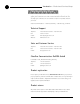
iii GT1524 Installation and Operation Manual Table of Contents CHAPTER 1: Introduction . . . . . . . . . . . . . . . . . . . . . . . . . . . . . . . . .1 Features . . . . . . . . . . . . . . . . . . . . . . . . . . . . . . . . . . . . . . . . . . . . . . . . .1 Professional Services Group . . . . . . . . . . . . . . . . . . . . . . . . . . . . . . . . . . .2 Technical Support . . . . . . . . . . . . . . . . . . . . . . . . . . . . . . . . . . . . .2 Sales and Customer Service . . . . . . . . . . . . . . .
iv APPENDICES . . . . . . . . . . . . . . . . . . . . . . . . . . . . . . . . . . . . . . . . . .19 Appendix A: Specifications . . . . . . . . . . . . . . . . . . . . . . . . . . . . . . . . . . . .19 Appendix B: Pinouts . . . . . . . . . . . . . . . . . . . . . . . . . . . . . . . . . . . . . . . . .20 Appendix C: Serial Commands . . . . . . . . . . . . . . . . . . . . . . . . . . . . . . . . .21 Appendix D: Warranty . . . . . . . . . . . . . . . . . . . . . . . . . . . . . . . . . . . . . . .
CHAPTER 1: Introduction The GT1524 provides the highest possible audio quality available in a single channel echo canceller. It features an integrated telephone interface that enables telephone participants of an audio or video conference to sound as if they are actually in the same room. Plus, it features simultaneous two-wire/four-wire operation so you can audio conference and video conference at the same time. And there’s no white noise setup; the GT1524 adapts automatically.
2 Introduction ~ Professional Services Group Professional Services Group If you need any additional information on how to install, set up, or operate your system, please contact us at one of the locations listed below. We welcome and encourage your comments so we can continue to improve our products and serve your needs. ClearOne Communications ~ 1825 Research Way ~ Salt Lake City, UT 84119 Technical Support Telephone: 1.800.283.5936 (USA) or 1.801.974.3760 Fax: 1.801.977.0087 E-mail: tech.
3 Introduction ~ Unpacking Unpacking Ensure that the following items were received with your shipment: GT1524 Enter Esc +12 +8 +4 0 -4 -10 -30 Telephone Meter On Off GT1524 PART 910-114-101 AC Power Cord PART 699-150-006 12-foot Telephone Cable PART 830-000-012 Push-on Blocks (6) PART 673-016-003 Optional Microphones PART 910-103-160 or 910-103-161 Mic Cables included (shown below) ✍ ClearOne Communications is not responsible for product damage incurred during shipment.
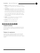
4 Introduction ~ Controls and Connections C. LED Meter. The LED bar meter displays the audio level of any input or output of the GT1524 as well as the Echo Return Loss (ERL) and Echo Return Loss Enhancement (ERLE) between the Speaker/Line Out and the Mic/Line audio input channel. The LED meter also displays Telco Echo Return Loss (TERL) and Telco Echo Return Loss Enhancement (TERLE) for the telephone hybrid. D. Meter.
Introduction ~ Operational Requirements E. RS-232. This female DB-9 serial port is for interconnection between the GT1524 and a PC or custom remote control. See Appendix C for serial port commands. F. Control/Status. This female DB-25 connector is used to interface parallel control and status to the GT1524. Control pins on this connector are used to perform functions via a momentary closure to ground. Each status pin on this connector shows the state of the function handled by the pin.
6 Technical Services Group ~ 1-800-283-5936 (USA) ~ 1-801-974-3760
CHAPTER 2: Installation Hardware Setup This chapter provides step-by-step instructions for installing your GT1524 system. Figure 2.1 (below) shows the back panel connections of a fully-installed GT1524 system. 5W, 8Ω Speaker Analog Telephone Line 4 WIRE/VIDEO CODEC LINE OUT IN AUX OUT MIC/LINE IN OUT AUX IN Logic out status and control Power Amp Microphone Video codec MUTE IN USE READY AP IR Remote Control Figure 2.1.
8 Installation ~ LCD Programming ✍ The three terminals in the Phoenix connector correspond with the rearpanel audio contacts (from left to right): + (positive), – (negative), and (ground). 5. Use the RS-232 port to connect the GT1524 to a PC (for use with HyperTerminal), an AP IR Remote Control, or a custom remote control device. 6. Connect an external amplifier or sound reinforcement system to Line Out. Use Aux Out to connect recording equipment, such as a VCR. Nominal output is 0dBu. 7.
9 Installation ~ LCD Programming appropriate menu. Then press Enter. To descend a menu level (go deeper into the tree), press Enter. To ascend a menu level (go back toward the top of the tree), press ESC. Enter Esc The Meter button will also access the Meter tree directly. The menu trees are structured in levels, such that the first level (top of the tree) branches into multiple +12 +8 +4 0 -4 -10 -30 Meter Figure 2.5. Front Panel Buttons subcategories (see Figure 2.7).
10 Installation ~ LCD Programming Power-Up Screen ClearOne GT1524 Ve rsio n x.
Installation ~ LCD Programming Inputs There are four main submenus under the Inputs menu tree: Mic/Line In, Aux In, 4 Wire In, and From Telco (see Figure 2.7). Mic/Line In Gain Adjust. This adjusts the Mic/Line In submenus, including the level for the Input gain (ranging between -20dB and 20dB). The default setting is 0dB. Mic/Line Input. This input defaults as a line-level input (0dB gain) but can be switched to a mic level input (55dB or 25dB gain). Mute. This parameter mutes the input channel.
12 Installation ~ LCD Programming AGC. The input can use automatic gain control (AGC). This feature keeps softer and louder talkers at a consistent transmit level. This feature is disabled when shipped from the factory. The target gain is 0dB and adjusts at 2dB per second. The AGC start adjustment is -20dB, but will adjust only +6dB. Adjustments will not be made at .5dB on either side of the target (0dB).
Installation ~ LCD Programming To lock the front panel 1. Enter the System menu 2. Scroll through the menu items to select Lock Panel, and press Enter. 3. Select On, and press Enter again. To unlock the front panel 1. 2. Attempt to adjust a parameter. The GT1524 prompts you for the passcode. Begin entering the passcode. Once you have correctly entered the fifth character, the front panel unlocks. (The default passcode for all units is Up, Up, Down, Down, Enter.
14 Installation ~ LCD Programming Ring Indication. An audible ring indicator, sent to the PA output, can be enabled or disabled under this menu. Unit ID Number The Unit ID # allows you to view the read-only unit address set at the factory. This unique ID number identifies that particular unit and cannot be changed. Meters There are five main submenus under the meter menu tree: Inputs, Outputs, ERL/TERL, ERLE/TERLE, and Default Meter. The first four submenus are all handled in the same way.
CHAPTER 3: Operation A correctly installed GT1524 virtually runs by itself. Typical operations involve changing volume of an output, muting an input or output, or handling calls on the connected telephone handset. For most installations, a custom remote control (optional) is also used. Front Panel Control Controlling volume When participating in a conference, you might find it necessary to increase or decrease the volume of a particular output.
16 Operation ~ Front Panel Control Answering a call An incoming call rings on the telephone set connected to the GT1524 (and speaker, if one is connected to the GT1524) and causes the On LED to flash. There are four ways to answer an incoming call: ✍ If Auto-Answer is turned On under System settings, the GT1524 answers the call after the second complete ring. A ringing tone is provided to the Line and Speaker output if Ring Indication is turned on.
17 Operation ~ Custom Control Custom Control Custom controller options The GT1524 is designed to function with remote control systems. The controller is connected to the GT1524 through the RS-232 port. The AP IR Remote also functions with the GT1524.
18 Technical Services Group ~ 1-800-283-5936 (USA) ~ 1-801-974-3760
Appendices Appendix A: Specifications Dimensions (LxDxH) Telco Line 17.25" x 10.25" x 1.75" 43.8 x 26 x 4.5 cm Echo Cancellation: 120ms tail time (works with 12dB of room gain) Phantom Power: 24V, selectable Weight AUX In 7 lb/3.18 kg dry 12 lb/5.4 kg shipping Push-on terminal block, balanced, bridging Impedance: 20kΩ Nominal Level: 0dBu Maximum Level: 19dBu Telco Set 4 Wire/Video Codec In Unless otherwise specified, all measurements are performed with a 22Hz to 22kHz BW limit (no weighting).
20 Appendix B ~ Pinouts Appendix B: Pinouts Control/Status port pinout (female) 13 1 25 Definable Type Default Description 1 Yes Control Aux In to Aux Out toggle 2 Yes Status Status of Aux In to Aux Out 3 Yes Control Mute Mic/Line In toggle 4 Yes Status Status of Mic/Line In mute 5 Yes C Telephone On/Off toggle 6 Yes S Status of tel.
Appendix C ~ Serial Commands Appendix C: Serial Commands The GT1524 accepts serial commands through the serial port. The commands in this manual pertain only to the GT1524. RS-232 serial port protocol is 9,600 (default), 19,200, or 38,400 baud; 8 bits, 1 stop bit, no parity. Conventions The following typographic conventions are used in this document to describe the different serial commands. Use the Command structure section and the examples as a guide when creating your serial commands.
22 Appendix C ~ Serial Commands GT1524 Serial Commands Command Function AA Selects/Reports Auto Answer for Telco Port AD Selects/Reports Auto Disconnnect for Telco Port AGC Enables/Disables AGC† AUXMIX Enables/Disables Mic/Line In and Aux In to Aux Out BAUD Sets/Reports RS-232 Port Baud Rate DFLTM Sets/Reports Default Meter DIAL Sends Dial String to Telco Port EC Enables/Disables Echo Canceller ERL Returns ERL for the Mic/Line In Channel ERLE Returns ERLE for the Mic/Line In Channel
23 Appendix C ~ Serial Commands AA This command activates and deactivates the auto answer feature. Command form: AA Explanation Value 0 = Disables auto-answer 1 = Enables auto-answer 2 = Toggles between states (regardless of current state) Null = Reports back the current state Return values The command will return the updated condition (On=1, Off=0) of the auto answer in the same format as the command. AD This command changes the state of the auto disconnect function.
24 Appendix C ~ Serial Commands AUXMIX This command changes or reports back the state of the Aux Mix Out. Command form: AUXMIX Explanation Channel 1 = Mic/Line In, 2= Aux In Value 0 = Sets state to Off, 1 = Sets the state to On Return values The command will return the updated condition of the Aux Mix in the same format as the command. BAUD This command selects or returns the baud rate for the RS-232 port on the GT1524.
Appendix C ~ Serial Commands DIAL This command generates DTMF tones. This capability remains active after the call is placed so tones can be issued for use with voice mail and pagers. Command form: DIAL Explanation STRING is any valid combination of touch tone characters. A comma indicates a two-second pause. STRING has a maximum length of 15 characters. Valid characters are 0 through 9, A through D, *, # and “,”. Return values DIAL returns the dialed string of numbers.
26 Appendix C ~ Serial Commands FLOW This command selects or reports whether hardware flow control is enable or disabled for the GT1524. Hardware flow control is implemented using RTS and CTS. Command form: FLOW Explanation Value 0 = Sets flow control to Off 1 = Sets flow control to On Null = Returns the current mode Return values The command will return the updated condition (On=1, Off=0) of the GT1524 in the same format as the command.
Appendix C ~ Serial Commands Example The following command lowers the gain 3dB on the Mic/Line input channel. GAIN 1 I -3 HOOK This command sends a momentary interruption in the line seizure (hook flash) to the telephone line. Command form: HOOK Return values If hook flash succeeded, the following is returned out the port: HOOK 0 HOOKD This command controls and reports the Hook Duration of the unit.
28 Appendix C ~ Serial Commands LVL This command reports back the level for a given channel. Command form: LVL Explanation Channel 1 2 3 4 = = = = Mic/Line Input, Line Output Aux Input, Aux Output 4 Wire Input, 4 Wire Output Telco Input, Telco Output Value I = Specifies an input meter O = Specifies an output meter Return values The command will return the input level of the channel in the same format as the command.
Appendix C ~ Serial Commands MUTE This command changes or reports the state of mute for a given channel.
30 Appendix C ~ Serial Commands PP This command changes or reports back the state of the phantom power for a microphone. Command form: PP Explanation Value 0 = Sets the state to Off 1 = Sets the state to On Null = Returns the current state Return values The command will return the updated condition (On=1, Off=0) of the phantom power in the same format as the command. RING This command reports the presence of a Ring on the Telco port. (This is an indication only.
Appendix C ~ Serial Commands TAMODE This command controls or reports the Telephone Adapt Mode control of the unit. Command form: TAMODE Explanation Value 0 = Sets Telephone Adapt Mode to Auto 1 = Sets Telephone Adapt Mode to Burst Null = Reports back the current state Return value The command returns the updated connection state of the unit in the same format as the command. TE This command controls or reports the connection status of the unit.
32 Appendix C ~ Serial Commands TOUT This command sets or reports the current inactivity timeout before returning to the menu screen used by the unit. Command form: TOUT Explanation Value 0 = Disables inactivity timeout 1–15 = Sets the number of minutes specified Null = Returns the current number of minutes Return Values The command will return the current timeout value. If the command changed the timeout, the updated timeout is returned.
Appendix D ~ Warranty Warranty ClearOne Communications, Inc. (Manufacturer) warrants that this product is free of defects in both materials and workmanship. Should any part of this product be defective, the Manufacturer agrees, at its option, to: A. Repair or replace any defective part free of charge (except transportation charges) for a period of one year from the date of installation for the enduser, provided the owner returns the product to the Manufacturer at the address set forth below.
34 Appendix E ~ Compliance Manufacturer shall not be liable for punitive, consequential, or incidental damages, expenses, or loss of revenue or property, inconvenience, or interruption in operation experienced by the end user due to a malfunction in the purchased product. No warranty service performed on any product shall extend the applicable warranty period.
Appendix E ~ Compliance USOC Jacks: This device uses RJ11C and RJ21X terminal jacks. The REN is used to determine the quantity of devices which may be connected to the telephone line. Excessive RENs on the telephone line may result in the devices not ringing in response to an incoming call. In most, but not all areas, the sum of the RENs should not exceed five (5).
36 Appendix E ~ Compliance give the telecommunications company cause to request the user to disconnect the equipment. Users should ensure for their own protection that the electrical ground connections of the power utility, telephone lines and internal metallic water pipe system, if present, are connected together. This precaution may be particularly important in rural areas. European compliance (for international unit part no.
37 Index ~ A–R Index 4 Wire In 4, 8, 19 4 Wire Out 4, 8, 12, 19 A acoustic echo cancellation 1 AGC 11, 12 H high-pass filter 11 I inputs 14 installation 7 answering a call 16 AP IR Remote 8 auto-answer 13, 16 auto-disconnect 13, 16 Aux In 4, 11, 19 Aux Out 4, 8, 12, 19 Aux Out Mix 12 L LCD display 3, 8 LCD panel 14 LCD programming 8 Line Out 4, 8, 19 Lock panel 12, 13 loop drop 13 B loop drop + CP 13 baud 13 M C making a call 16 call progress 13 control/status 5, 7, 19, 20 Meters 4, 14 Mic/Li
38 Index ~ S–Z S TERLE 4, 14 serial commands 21 timeout 14 set passcode 12, 13 To Telco 12 speaker 5, 8 touch-tone dialing 1 Speaker/Line Out 12, 19 two-wire/four-wire operation 1 system 12, 13 U T Unit ID 12, 14 unmute 15 technical support 2 telco 12, 13, 19 telco echo cancellation 1 V Telco Line 5, 19 video codec 8 Telco Set 5, 19 Video Codec In 4, 8, 19 telephone handset 16 Video Codec Out 4, 8, 19 TERL 4, 14 volume control 15 Technical Services Group ~ 1-800-283-5936 (USA) ~ 1-8
www.gentner.