PSR1212 Digital Matrix Mixer Installation & Operation Manual
ii ©2002 ClearOne Communications, Inc. All rights reserved. No part of this document may be reproduced in any form or by any means without written permission from ClearOne Communications, Inc. Printed in the United States of America. ClearOne Communications, Inc. reserves specific privileges. Information in this document is subject to change without notice. PSR1212 Installation and Operation Manual ClearOne Part No. 800-155001 Jan 2007(Rev. 7.
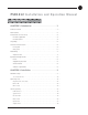
iii PSR1212 Installation and Operation Manual Table of Contents CHAPTER 1: Introduction . . . . . . . . . . . . . . . . . . . . . .1 Product overview . . . . . . . . . . . . . . . . . . . . . . . . . . . . . . . . . . . . . . . . .1. . . . New Features . . . . . . . . . . . . . . . . . . . . . . . . . . . . . . . . . . . . . . . . . . . .2. . . . Professional Services Group . . . . . . . . . . . . . . . . . . . . . . . . . . . . . . . . . .3. . . Product registration . . . . . . . . . . . . . . . . . .
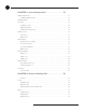
iv CHAPTER 3: System Configuration . . . . . . . . . . . . . . . .21 G-Ware Requirements . . . . . . . . . . . . . . . . . . . . . . . . . . . . . . . . . . . . . . . . . . . . . . . . Creating Floppy Disk Copies . . . . . . . . . . . . . . . . . . . . . . . . . . . . . . . . . . . . . Installing G-Ware . . . . . . . . . . . . . . . . . . . . . . . . . . . . . . . . . . . . . . . . . . . . . . . . . . . 21 22 22 Site Setup . . . . . . . . . . . . . . . . . . . . . . . . . . . . . . . . . . . . . . . . . .
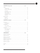
v CHAPTER 5: Operation . . . . . . . . . . . . . . . . . . . . . . . .65 Utilities . . . . . . . . . . . . . . . . . . . . . . . . . . . . . . . . . . . . . . . . . . . . . . . . . . . . . . . . . . . 65 Signal Generator . . . . . . . . . . . . . . . . . . . . . . . . . . . . . . . . . . . . . . . . . . . . . 65 Document Compare Utility . . . . . . . . . . . . . . . . . . . . . . . . . . . . . . . . . . . . . . 66 Print Reports . . . . . . . . . . . . . . . . . . . . . . . . . . . . . . . . . . . . .
vi Technical Services Group ~ 1-800-283-5936 (USA) ~ 1-801-974-3760
CHAPTER 1: Introduction Product overview Congratulations on purchasing the PSR1212, a highly advanced twelve-by-twelve digital matrix mixer with audio processing. It utilizes an internal macro language and 32 user-definable presets to quickly adapt to a variety of sound reinforcement and room-combining applications in auditoriums, stadiums, theatres, gymnasiums, hotel/convention centers, conference rooms, training rooms, and boardrooms.
2 Introduction ~ New Features New Features • Virtual references. The PSR1212 now features four user-definable virtual references. These references can use multiple signals as the PA Adapt reference point without sacrificing an analog output. • Front panel gain and mute control. Now gain and mute adjustments can be made from the front panel. Using these controls allows you to make quick volume and mute changes without connecting through G-Ware. • Safety Mute.
Introduction ~ Professional Services Group Professional Services Group If you need any additional information on how to install, set up, or operate your system, please contact us at one of the locations listed below. We welcome and encourage your comments so we can continue to improve our products and serve your needs. ClearOne Communications ~ 5225 Wiley Post Way, Suite 500 Salt Lake City, Utah 84116 Technical Support Telephone: 1.800.283.5936(USA) or 1.801.974.3760 Fax: 1.801.977.0087 E-mail: tech.
4 Introduction ~ Unpacking Unpacking Ensure that the following items were received with your shipment: ClearOne is not responsible for product damage incurred during shipment. You must make claims directly with the carrier. Inspect your shipment carefully for obvious signs of damage. If the shipment appears to be damaged, retain the original boxes and packing material for inspection by the carrier. Contact your carrier immediately. ! Figure 1.1.
5 Introduction ~ Controls and Connections C. s/tThese buttons scroll up and down through vertical programming options within a specific PSR1212 programming parameter or increases/decreases a numeric value. D. Esc. This button steps you out of a selected parameter or moves you up one level in the menu. When a parameter has been displayed with the arrow buttons [C], you can select it with the Enter button [B] to modify it. Then, you can step out of the menu with the Esc button. E. LED meter.
6 Introduction ~ Controls and Connections Power is supplied through the RS-485 ports to the remote Control Panels from the PSR1212. This power is limited to a total of 300mA at 15 volts for each connector. Over-current protection is provided on the +15V pins to prevent damage in the event of shorting. External power can be provided to control devices when more current is required. See page 89 for maximum cable run distances when using ClearOne Control Panels. D. Control/Status Ports A and B.
7 Introduction ~ Networking Networking Expansion bus The digital mix-minus expansion bus (RJ-45 LAN) is used to connect up to eight PSR1212s (or XAP 800/400s and 16 XAP TH2 units), where the total number of microphone inputs does not exceed 64. The maximum distance between interconnected PSR1212 or XAP 800/400 units is 80 feet (24 meters). Connecting a XAP TH2 must not increase the cable length between two PSR1212s, XAP 800s and/or XAP 400s beyond 80 feet.
8 Introduction ~ Operational Requirements Operational Requirements Power The PSR1212 automatically accommodates voltage requirements of 100–240VAC, 50/60Hz, 15W. Equipment placement The PSR1212 units are designed for installation in a standard 19-inch equipment rack. You can also purchase side panels for desktop placement. See Appendix D for a list of accessories. Environmental The PSR1212 can be safely operated in a room with varying temperatures between 32 ° F/0 ° C and 110 ° F/43 ° C.
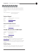
CHAPTER 2: Installation The PSR1212 is designed for easy installation and setup. All connections are made through rear-panel connectors. This chapter provides instructions on making hardware connections, creating an expansion bus network, assigning device ID numbers, selecting the mixer mode, and using the front panel LCD menus. Hardware Setup The diagram below illustrates the typical connections that are made for a PSR1212 system. ClearOne Figure 2.1.
10 Installation ~ Hardware Setup Expansion Bus In Out Figure 2.2. PSR1212 rear-panel connectors To connect the unit 1. Place the unit in a standard 19-inch rack and attach it securely. 2. If you are using a custom controller for control and status, plug it into the DB-25 Control/Status A or B port [D]. If you are using an external RS-232 controller, connect it to the RS-232 port [I].
11 Installation ~ Networking Units Networking Units Expansion bus connections Using the Expansion Bus ports (RJ-45), you can connect up to eight PSR1212s or XAP 800/400s and 16 XAP TH2 units, where the total number of microphone inputs does not exceed 64. Make connections between units in daisy-chain fashion using the short RJ-45 jumper. If your units are further apart, use category five twisted-pair cable. The maximum distance between interconnected PSR1212 or XAP 800/400 units is 80 feet (24 meters).
12 Installation ~ Networking Units If the same device ID is assigned to more than one unit on the E-bus network, the Meter LED “+12” will flash red and the Mic LEDs “1,” “2,” “4,” and “8” will flash green on the affected units. To correct the problem, change the device ID on one of the conflicting units.
13 Installation ~ LCD Programming LCD Programming The PSR1212’s front panel is intuitive to operate, thanks to its simple interface: a 2x16 character LCD, menu buttons, and a peak-level LED bar meter. Although most of the PSR1212’s features are programmed with G-Ware software (see page 23), - G-Ware software is required to complete system setup. the front panel can be used for simple adjustments and meter monitoring. When power is applied to the PSR1212, the LCD panel will first read INITIALIZING.
14 Installation ~ LCD Programming The five main menus are: System, RS-232, Meter, Inputs, and Outputs. All submenu items are arranged under these menus. Use the Enter button to select items and the s and tbuttons to scroll through menus and submenus. When the last menu item is reached, the display scrolls back to the beginning of the list. The Esc button allows you to back out of the menus. To adjust a parameter 1. Scroll to the parameter you want to adjust. Press Enter to select the parameter.
15 Installation ~ LCD Programming To unlock the front panel, attempt to adjust a parameter. The PSR1212 will prompt for the passcode. Upon entering the fifth character (if entered correctly), the front panel will unlock. The default passcode for all boxes is sstt Enter. Set Passcode Once the PSR1212 is unlocked, the passcode can be changed. Before the PSR1212 will allow passcode changes, the new passcode must be entered, then re-entered to validate the new passcode.
16 - Installation ~ LCD Programming ClearOne recommends that you leave Flow Control enabled. Flow Control (hardware) The PSR1212 uses the RTS and CTS pins on the RS-232 port to regulate the transmission and reception of data. You can enable or disable flow control on the front panel of unit and select the flow control type in the Site Properties window of G-Ware (see page 23). If you select On (default) from the front panel menu, select Hardware as the flow control type in the Site Properties window.
Installation ~ LCD Programming Inputs Select which input (1–12) you want to monitor on the LCD and LED display. Scroll to the input, then press Enter. The meter displayed is the post-gain meter. Outputs This submenu allows you to choose which output (1–12) you want to monitor on the LCD and LED display. Scroll to the output you want to monitor, then press Enter. Processing This submenu allows you to choose which processing channel (A–H) you want to monitor on the LCD and LED display.
18 Installation ~ LCD Programming Outputs menu There are two submenus under the Outputs menu: Mute and Gain. To access these submenus you must first select the output. Choose from Outputs 1–12. Use the s and tbuttons to select the Outputs menu, then scroll through the options and press Enter when you reach the desired option. Mute This submenu allows you to turn mute on or off (default) for the selected output. Gain This submenu allows you to adjust the gain for the selected output.
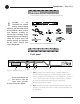
M M Off On M Off On Off NOM On Mute Output Gain Post-gain Meter Output 3 Technical Services Group ~ 1-800-283-5936 (USA) ~ 1-801-974-3760 Phantom Power On/Off Input 1 Input 2 On Off Mute Input Processing M Mic 55, 25 Line Pre-gain Meter All Pass Low Pass High Pass Notch PEQ Input 4 Off On M Off On Off NOM On Mute Output Gain Post-gain Meter Output 7 M On Off Pre-gain Meter M Mic 55,25 Line Automixer Input 7 Input 8 M M M M Pre-gain Meter M Off On Off On Input 10
20 Technical Services Group ~ 1-800-283-5936 (USA) ~ 1-801-974-3760
CHAPTER 3: System Configuration ClearOne’s G-Ware software provides an easy interface for configuring and controlling your PSR1212. While some configuration can be done using the front panel LCD menus, G-Ware is required to complete the custom configuration of your audio conferencing system. If you are using the default settings, no configuration is necessary. This chapter describes how to install G-Ware and create a site. It also describes all configurable parameters of your system.
22 System Configuration ~ Installing G-Ware Creating Floppy Disk Copies Depending upon the computer equipment you have available, you might need to install G-Ware software from floppy disks rather than the included CD. To do this, a Disk Copy program is provided in G-Ware that allows you to transfer G-Ware to floppy disks. You will need a PC with a CD-ROM drive to make the transfer.
23 System Configuration ~ Site Setup Site Setup Creating a new site New site files are created through the Site Properties window in G-Ware. A site file contains all information about a particular installation including all unit settings and left Whenever a mouse click is indicated in this manual, it refers to the mouse button unless properties. It also provides G-Ware with the necessary information to communicate with the site hardware using your PC.
24 System Configuration ~ Site Setup Adding a PSR1212 You can add a PSR1212(s) to your site file by connecting to your site and using G-Ware to automatically create icons for the detected units. Or, you can work offline and manually add the unit(s) to the site file and connect to the site at a later time. To open an existing site file, click the Open Site File button or select Open Site from Figure 3.6. Open Site File button the File menu. To auto-detect units 1.
25 System Configuration ~ Site Setup Configuring Unit Properties Using the Unit Properties window, you can configure the unit’s communication and security properties in addition to general unit properties such as name and type. The Unit Properties window automatically opens when you manually add a unit to the site. You can also right-click the unit icon in the site pane and click Unit Properties. To configure Unit Properties 1. Figure 3.11.
26 System Configuration ~ Site Setup 8. If a modem is connected to the PSR1212 unit, select Use Modem and enter the initialization string. Click OK; the PSR1212 will initialize the modem. 9. Click the Security tab. Create a modem password. The password will be required before control of the system through remote modem access is allowed. The default modem password is a carriage return. 10. Preset/Macro Password enables you to password protect your individual presets and macros.
27 System Configuration ~ G-Ware Screens G-Ware Screens G-Ware has three modes: Configuration, Preset, and Macro Recorder. Configuration is used to configure the unit and is the default mode. The Preset and Macro modes are discussed in Chapter 4: Advanced Configuration. You can switch between modes by clicking on the corresponding toolbar button. The current mode is displayed on the status bar. There are two main configuration screens, the Flow Screen and the Matrix Screen.
28 System Configuration ~ G-Ware Screens Copying and pasting settings G-Ware has shortcut menus which appear when you right-click a selection or program window in G-Ware. These shortcut menus provide quick access to options such as Print, Copy, and Paste that pertain only to that selection or screen region. Figure 3.17. Unit shortcut menu Using the Copy and Paste commands, you can copy and paste unit data such as a single setting or the entire unit’s settings depending on which window you are in.
29 System Configuration ~ G-Ware Screens Matrix Screen The Matrix Screen is used to route audio to one or more destinations (outputs, expansion bus, or processing). Any number of connections to outputs can be made in the matrix. The Matrix Screen can also be used to access the Input, Output, and Processing configuration windows by clicking on the buttons along the top and left sides of the routing matrix. Toolbar Menus Labels Site pane Matrix Screen Status bar Figure 3.20.
30 System Configuration ~ Audio Routing Audio Routing Audio is routed in the Matrix Screen (see Figure 3.20 on previous page). To access the Matrix Screen, click on the Matrix button on the Flow Screen. To return to the Flow Screen, click the Flow Screen button. The PSR1212 routing matrix has 32 possible input sources and 32 output destinations, with level control at each cross point. Any input or combination of inputs can be routed to any output or any combination of outputs.
31 System Configuration ~ Audio Routing numerical value directly in the window). The attenuation range is from 0 to 60dB. Click Close to exit. Note that the level control you have selected for the cross point is indicated numerically in the cross point cell. The Cross Point shortcut menu also allows you to copy and paste the current Cross Point configuration, including attenuation, to other cross points. You can copy a single cell or the entire matrix using the shortcut menu options.
32 System Configuration ~ Inputs and Outputs Inputs and Outputs - Inputs 1–8 accept either microphone (-55, -25dB) or line level (0dB) Inputs 1–8 To open the Inputs 1–8 configuration window, click the Inputs 1–8 button on the Flow Screen. The In 1–8 button on the Matrix Screen will also open this window. These inputs are balanced and support both mic and line levels. Figure 3.25. Inputs 1–8 configuration window To select an input channel, click a blank area in the input pane.
System Configuration ~ Inputs and Outputs 12dB closer to the target. AGC occurs after the gain and filter settings in the audio signal path. AGC default is Off. P Pwr (Phantom Power) Phantom Power toggles the phantom power on and off. Phantom power is an auxiliary power source to power certain types of microphones. The PSR1212’s phantom power voltage is 24VDC. Default is On. Filters Figure 3.26.
34 System Configuration ~ Inputs and Outputs • Low Pass. Selectable frequency cutoff is 20Hz to 20kHz in 1Hz increments. Rolloff is 12dB/octave. Level is fixed at 0dB. • Notch. Center frequency range is 20Hz to 20kHz with resolution to 1Hz or four places (whichever is larger). Bandwidth is from .05 to 5 octaves in .01 octave increments. Level is fixed at -80dB. • PEQ (parametric equalizer). Center frequency range is 20Hz to 20kHz with resolution to 1Hz or 4 places (whichever is larger). Bandwidth is .
35 System Configuration ~ Inputs and Outputs Figure 3.27. Filter Graph window, table view To configure filters 1. In either the graph or table view, select the filter type from the Type list. Note that the configurable filter parameters displayed depend on the selected filter type. 2. Click Add Filter to add a filter to the graph or table. 3. Configure filter parameters using the previously described lists.
36 System Configuration ~ Inputs and Outputs Chairman Override Chairman Override provides gating priority for this mic input over any other mic input within the same gating control (mixer) groups. When a mic with Chairman Override enabled gates on, all mics which don’t have Chairman Override enabled will gate off. Default is off. Adaptive Ambient Adaptive Ambient adjusts the ambient reference level as noise and room conditions change.
System Configuration ~ Inputs and Outputs Figure 3.29. PSR1212 automixing gate functions Ambient Level if you want to specify a fixed reference point rather than one that adjusts for background noise. The range is from -80 to 0dB. Default is Off. Decay Rate Decay Rate determines how fast a channel gates off after the hold time expires. Default is Medium. PA Adapt and AEC Reference When using the PA Adaptive mode, the output that carries this information, i.e. the reference output, must be defined.
38 System Configuration ~ Inputs and Outputs If you select a virtual reference, the Virtual Reference window will open. You can also open this window from the G-Ware toolbar. Figure 3.31. Virtual Reference toolbar button Figure 3.32. Virtual Reference window. Use this window to select which signals will be included in each of the four Virtual Reference points. The routing matrix portion of this window cannot be edited. Virtual references are used when you need to reference multiple outputs.
39 System Configuration ~ Inputs and Outputs Gating Group Select In addition to specifying gating characteristics for each mic input, you can assign the inputs to a gating group for greater flexibility and control. When inputs are assigned to a gating group, the gating information from the inputs is used to Figure 3.33. Gating Group Select pane control how the entire mixer behaves.
40 System Configuration ~ Inputs and Outputs 3. Leave 1st Mic Priority selected (default) to enable this feature; otherwise, clear the selection to disable it. ClearOne recommends leaving this setting on. This setting helps maintain maximum audio intelligibility by allowing only one mic to gate on to a participant’s voice. 1st Mic Priority allows more than one microphone to be activated at the same time— it simply restricts mics from gating on to the same audio source.
41 System Configuration ~ Inputs and Outputs commands are used. Optimizing input gain structure How you adjust an input’s gain directly affects sound quality. The optimal input gain setting is one which is adjusted as high as possible above the noise floor without introducing clipping. Clipping can cause distortion which can damage amplifiers and loudspeakers. To adjust the input level properly, place a signal on the input at the maximum level it will generate.
42 System Configuration ~ Inputs and Outputs Inputs 9–12 The PSR1212 supports four line level only inputs for auxiliary audio sources such as VCRs and CD players. To open the Inputs 9–12 configuration window, click the Inputs 9–12 button on the Flow Screen. The In 9–12 button on the Matrix Screen will also open this window. These non-gated inputs are balanced. The nominal input level is 0dBu. Figure 3.38. Inputs 9–12 Configuration window To select an input channel, click a blank area in the input pane.
43 System Configuration ~ Inputs and Outputs Gain The Gain slider on the selected input in the Inputs 9–12 window is used to adjust input volume level. • Max adju Use the Gain slider to adjust input volume level. You can also enter the level directly in the decibel box below the gain scale. M in adju Min/Max limits Use the yellow and blue upper and lower limit arrows on the Gain scale to create Figure 3.39. Gain adjust on line level input minimum and maximum gain level limits.
44 System Configuration ~ Inputs and Outputs Outputs 1–12 The PSR1212 has 12 line level outputs for sending audio to recorders or amplifiers. To open the Outputs 1–12 configuration window, click the Outputs 1–12 button on the Flow Screen. The Outputs 1–12 button on the Matrix Screen will also open this window. Figure 3.41. Outputs 1-12 configuration window These line level outputs are balanced. The nominal output level is 0dBu. The outputs can adjust from -65 to 20dBu.
45 System Configuration ~ Inputs and Outputs passing NOM information. Enable NOM if you want to place this output in a constant gain mode. Default is on. When enabled, the NOM button light illuminates green. Gain The Gain slider on the selected output in the Outputs 1–12 window is used to adjust output gain level. • Use the Gain slider to adjust output volume level. You can also enter the level Max adjust M in adjust directly in the decibel box.
46 System Configuration ~ Expansion Buses Expansion Buses Routing of audio to the expansion buses is done in the Matrix Screen. See page 30. For information on setting up an expansion bus network, see page 11. - From Expansion Bus O–Z Click the From Expansion Bus O–Z button on the Flow Screen to open the From Expansion Bus Labels window. You can also access this window from the Matrix Screen. Figure 3.43.
System Configuration ~ Processing Processing Processing A–H There are eight processing blocks in the PSR1212, each with filters, compressors, and delay to provide pinpoint audio configurations. To open the Processing configuration window, click the Processing A–H button on the Flow Screen. The To and From Processing buttons on the Matrix Screen will also open this window. Figure 3.45. Processing window To select a processing block, click a blank area in the Process pane.
48 System Configuration ~ Processing Cmprs (compressor) Cmprs opens the Compressor Setup window (see Figure 3.46). With the compressor you can change the gain transfer characteristics of the signal path and control the dynamics of a signal. When the signal exceeds the threshold level, gain reduction occurs at the rate specified by the reduction ratio. The attack time determines how aggressively the compressor reacts to increases in level.
System Configuration ~ Processing Post Compressor Gain Adjust the compressor gain with the gain slider or by using the s and tbuttons. The graph reflects the input/output decibel levels with the gain setting you select. Threshold Threshold determines the RMS level at which the compressor begins to operate. The range is from -30 to +20dBu. Default is 0dBu. Ratio Ratio changes the rate of compression applied to the input signal as the signal exceeds the threshold level. The range is 1:1 to 1:20.
50 System Configuration ~ Processing The frequency response and phase vs frequency of the total transfer function of all filters is displayed in the window. Each filter can be disabled without affecting the filter settings. All filters can also be disabled using a single command. By default, they are not enabled and the filter types are not defined. Below is a description of each feature in the window. Active Filter The Active Filter displays the filter that is applied to the processing channel.
51 System Configuration ~ Processing Figure 3.48. Low/Mid/High Loudspeaker Driver configuration Refer to the figure above. Note that as you create filters across several processing channels, you can observe their crossover points and general shape of the frequency response. In this case, several Linkwitz-Riley filters are being created across three processing channels to establish a balanced frequency response from low-frequency, midrange, and high-frequency transducers.
52 System Configuration ~ Processing Introducing an appropriate amount of delay to the forward-mounted driver(s) re-establishes the acoustical alignment necessary for proper sound imaging in a room. The same principle of introducing delay applies to separate speaker enclosures located various distances from the listening area. Other types of delay to consider when establishing delay parameters are delays which occur naturally as a result of processing operations within the PSR1212.
CHAPTER 4: Advanced Configuration Presets Overview For many audio conferencing applications, a great deal of system flexibility is needed to meet the challenges presented by changing meeting or conference room requirements. These requirements might include changes in muting, audio sources, room orientation, or room combining. And ideally, these changes are made instantaneously— without interrupting or affecting any meetings in progress.
54 Advanced Configuration ~ Presets G-Ware Toolbar G-Ware Menus Preset Configuration Pane Preset Matrix Screen Status Bar Figure 4.2. Preset Mode Matrix Screen The Matrix Screen in the Preset Mode is very similar to the Matrix Screen in Configuration Mode. All Input, Output, and Processing windows can be accessed by clicking on their respective buttons. You can also create custom labels by clicking on the current labels. The routing matrix is grayed out because no routing changes have been made.
55 Advanced Configuration ~ Presets Preset Description. Use the Preset Description box for entering information about the preset. This description is stored in the site file, not the unit. Preset Mask Control/Status B. With Preset Mask Control Status B you can require an active high (H) or active low (L) contact on a control pin (1–19 odd numbers) or combination of several contacts in order to run the preset. A typical use for Preset Mask Control Status B is a room combining Figure 4.4.
56 Advanced Configuration ~ Presets Virtual Reference. The Virtual Reference button opens the preset Virtual Reference window. Using the Virtual Reference window, you can select which signals will be used by the four Virtual Reference points in this preset configuration. The only input rows which will be shown in this window are the input rows which are active in the Preset Matrix Screen. The routing matrix (right pane) in this window is read-only.
Advanced Configuration ~ Presets To create a preset 1. From the Preset Selection list, select the number of the preset you will be configuring. Enter a description of the preset in the Preset Description box. 2. If you want to password protect this preset, click Protected. See page 26 for information on creating the preset password. 3. Configure the routing matrix and make cross point attenuation adjustments. 4. Configure input, output, and processing channel settings as needed.
58 Advanced Configuration ~ Presets Running presets Presets can be run from G-Ware or the front panel controls on the PSR1212. You can also program external control devices (such as AMX or Crestron, ClearOne Control Panels, XAP IR Remote, and GPIO devices) or use macros to run presets. See Chapter 6: Control for more information on creating custom control. To run a preset using G-Ware Figure 4.7. Execute Preset toolbar button 1. Select the Execute Preset button on the G-Ware toolbar. 2.
59 Advanced Configuration ~ Presets Figure 4.9. Assigning a state to a preset command in the Macro Editor If a preset is flagged as “On,”nothing will happen when the preset is executed again because the system knows it has already been run. This prevents any manual adjustments that are made during the course of the meeting (gain, muting, etc.) from being lost. Room combining example In the room combining scenario depicted in Figure 4.
60 Advanced Configuration ~ Presets The four macros (one for each configuration) are set up as follows: 4 4 4 4 4 4 4 4 4 4 4 4 4 4 4 4 4 4 4 4 4 4 4 4 When the room is in Configuration 1, running the Configuration 2 macro will change the presets to the following states: • P1 does not change because the flag is already set (1) • P2 and P3 clear their states (0) so they can be run • P4 runs and sets its state to on (1) which prevents other presets from rerunning it • P5 and P6 clear their states
61 Advanced Configuration ~ Macros Macros A macro is a series of commands which can be run from G-Ware, the front panel controls, or by using any external control device. Macros streamline the operation of the PSR1212, allowing you to make quick configuration changes and, as previously discussed, making it possible to execute multiple presets simultaneously (see pages 58–60). Macros can also contain commands that are executed on other XAP units.
62 Advanced Configuration ~ Macros To create a macro using Macro Editor 1. Click the Macro Editor button in the G-Ware toolbar to open the Macro Editor. Figure 4.14. Macro Editor button Figure 4.15. Macro Editor window 2. Select the Macro (from 1 to 255) you are creating from the Macro list. Numbers that are already assigned to macros will be marked with an asterisk. 3. Select the Protected check box to lock your macro. Locked macros are indicated by a padlock icon.
Advanced Configuration ~ Macros 9. Click Add to place the command into the macro. The command line now appears in the command line table. You can now create another command line for the macro or save the completed macro. Editing macros With the Macro Editor, you can add, edit, or remove command lines in the macro. If you used the Macro Recorder to create a macro, the Macro Editor opens automatically. Otherwise, click the Macro Editor toolbar button. To edit a macro 1.
64 Advanced Configuration ~ Macros Running macros Macros can be run from G-Ware or the front panel controls on the PSR1212. You can also run a macro using external control devices (see Chapter 6: Control for more information). To run a macro using G-Ware Figure 4.17. Run Macro toolbar button 1. Select the Run Macro button on the G-Ware toolbar. 2. Select the macro from the Select Macro list. Figure 4.18. Run Macro window 3. Click Run to run the macro and close the window.
CHAPTER 5: Operation G-Ware features several tools designed to assist you as you install your PSR1212 Digital Matrix Mixer including Signal Generator, Document Compare, Print Reports, Copy and Paste, and Message Log. G-Ware also provides Gate Views and Meters so you can quickly monitor or troubleshoot your system. This chapter describes how to use these utility programs and monitoring views in G-Ware. Utilities Signal Generator Figure 5.1.
66 Operation ~ Utilities To use tone 1. Select the PSR1212 Unit and Input Channel the signal will be generated on. 2. Select Tone. 3. Using the Frequency slider, select a specific tone frequency. You can also enter the frequency in the box directly below the Frequency slider. – or – Use the Auto Sweep button to sweep a range of frequencies. Select the Begin Frequency, the End Frequency, the Increment, and the Rate.
Operation ~ Utilities Figure 5.5. Open window 4. Repeat steps 1–3 to select the second second unit, site, or file for comparison. When you click Open, G-Ware automatically compares information from the selected items and displays a table of parameters which differ (note that the actual differences are not displayed at this point). This process can take a minute or two. Figure 5.6. Document Compare Utility showing two PSR1212 sites.
68 Operation ~ Utilities Figure 5.7. Print Preview window 6. To print the report, click Print (you can also click Print in the Compare Utility window to print the report). The other buttons in this window allow you to tailor the view of the report and browse sequentially through each page. 7. When you finish viewing or printing the report, close the Print Preview window to return to the Document Compare Utility.
Operation ~ Utilities In the window shown in Figure 5.8, clicking the Site 1 button transfers the selected settings from a line selected in the Site 2 column to the corresponding line in the Site 1 column. The Copy button copies the settings of the Site/Line above it, allowing you to paste (with the Paste button) settings to another site, unit, or even to a particular G-Ware parameter, such as an input.
70 Operation ~ Utilities Make a note of the baud rate selected in the Site Properties window before opening the G-Ware Firmware Utility. - GFirm Firmware Utility To make it easy to upgrade your unit when new firmware enhancements are released, G-Ware features a built-in firmware upgrade utility. Before upgrading firmware, save a copy of your site files and verify that the flow control setting on the unit (RS-232 menu on front panel LCD) is enabled.
71 Operation ~ Utilities 5. Select the PC COM port you are using for the upgrade. Select the Baud Rate that matches the baud rate in the Site Properties window. Figure 5.13. Selecting baud rate 6. Click Next. If the upgrade requires you to save your site files, a warning message will display. You will need to exit the G-Ware Firmware Utility, sync to the units with G-Ware, and save the site file(s) if you have not done so already. Click Yes, Continue to begin firmware upload. 7.
72 Operation ~ Utilities G-Ware Switcher G-Ware Switcher allows you to alternate between different G-Ware software versions that are installed on the same PC. For example, if you need to upgrade the firmware on your ClearOne unit(s), G-Ware Switcher allows you to easily switch to an earlier version of G-Ware (such as 3.5), save the site files, and then switch to a later version (4.5) to upgrade the firmware. Prior to the 4.
73 Operation ~ Monitoring Views If the selected G-Ware version is not active, click Re-Register/Make Shortcuts to re-register the version so it becomes active. Then click Run to launch it. If you have installed a version of G-Ware that isn’t displayed in the G-Ware Switcher window, click Refresh. G-Ware Switcher will locate and display the version. Copy and paste settings In most areas of G-Ware software, right-clicking the mouse opens a shortcut menu.
74 Figure 5.21. Gate View window Meter Views The Meter Views window allows you to monitor the level of any input, output, or processing signal of the PSR1212. You can monitor the same parameter on multiple Figure 5.22. Meters button inputs (or outputs or processing channels) for comparison or you can monitor an entire signal flow from input to output. Click the Meters button on the G-Ware toolbar to open this window. Figure 5.23. Meter Views window To configure Meter Views 1.
CHAPTER 6: Control There are many ways to control your PSR1212 and other networked units. This chapter explains how to set up control for Control/Status A port using GPIO Builder, XAP IR Remote and ClearOne Control Panel using Remote Builder, and RS-232 port. GPIO Builder Control/Status A GPIO stands for general-purpose input/output. The GPIO Builder is used to establish the pin assignments for the 16 user definable pins on Control/Status Port A.
76 Control ~ Remote Builder Remote Builder The Remote Builder window is used to configure the optional XAP IR Remote Control and ClearOne Volume and Select Control Panels. These control devices are connected to Remote Panel A or Remote Panel B— the RS-485 connectors. If you want to create custom control assignments for presets, open the Remote Builder from the Preset Configuration pane and select the Use in Preset option.
77 Control ~ Remote Builder To program the XAP IR Remote 1. Select an ID number for the remote from the Select Remote ID list. 2. Click Change Name to create a more descriptive name for the remote which is displayed in addition to the remote number (limit 20 characters). 3. Select IR Remote (default) from the Select Remote Type list. 4.
78 Each Control Panel button can be programmed to respond like a momentary or latching button. A command can be programmed to activate or deactivate a particular function. - Control ~ Remote Builder To program the Volume panel 1. Select an ID number for the remote from the Select Remote ID list. 2. Click Change Name to create a more descriptive name (limit 20 characters) for the remote which is displayed in addition to the remote number in the Select Remote ID list.
79 Control ~ Remote Builder 6. Select the Device Type, ID, and Command from their respective lists. When you select a command, a description of it appears in the Command Description box. 7. Select the command parameters from the argument lists. The parameters that are available depend on the command selected. When you select an argument, a description of it appears in the Argument Description box. 8. Click the Apply button to apply the command to the selected Active or Inactive command button.
80 Control ~ RS-232 Port 5. Click the Active Command or Inactive Command button to set the command for operation when the button is active or inactive. 6. Select the Device Type, ID, and Command from their respective lists. When you select a command, a description of it appears in the Command Description box. 7. Select the command settings from the argument lists. The options that are available depend on the command selected.
81 Control ~ RS-232 Port Command strings By creating command strings, you can use your PSR1212 to control equipment such as lighting, projectors, and room dividers as well as other ClearOne products. A command string is passed to the connected device via the PSR1212’s RS-232 port. You can create up to eight customized serial command strings (limit 80 characters each) in the Command Strings window. To open the Command Strings window, click the Command Strings toolbar button. Figure 6.7.
82 Technical Services Group ~ 1-800-283-5936 (USA) ~ 1-801-974-3760
APPENDICES Appendix A: Specifications Dimensions (LxDxH) Mic/Line Inputs 1-8 17.25" x 10.25" x 1.25" 43.8 x 26 x 4.5 cm Push-on terminal block, balanced, bridging Impedance: 5kž Nominal Level: adjustable -55dBu, -25dBu, 0dBu Maximum Level: -35dBu, -5dBu, +20dBu Phantom Power: 24V, selectable Weight 7 lb/4.5 kg dry 12 lb/5.
84 Appendices ~ Appendix B: Pinouts Appendix B: Pinouts 5 9 1 RS-232 COM DCE port pinout (female) Figure B.1.
85 Appendices ~ Appendix B: Pinouts Control/Status connectors 13 1 The Control/Status connections are provided on two DB-25 connectors. These connectors are labeled Control/Status A and Control/Status B and contain different 25 14 types of pins. The inputs on these connectors are internally pulled high and are activated by connecting the pin to ground. The outputs are open collectors, which Figure B.6. Control/Status Ports A, B are open when inactive and grounded when active.
86 Appendices ~ Appendix B: Pinouts Control/Status B port pinout Pin Definable* Type Default Description 1 No C Preset select bit 2 No S Preset select status for Pin 1 3 No C Preset select bit 4 No S Preset select status for Pin 3 5 No C Preset select bit 6 No S Preset select status for Pin 5 7 No C Preset select bit 8 No S Preset select status for Pin 7 9 No C Preset select bit 10 No S Preset select status for Pin 9 11 No C Preset select bit 12 No S Prese
87 Appendices ~ Appendix B: Pinouts RS-485 Remote Panel A and B connectors Pin Description 1 +15VDC, 300mA (over-current protected) 2 Data + 3 Data – 4 Ground 4 3 2 1 4 3 2 Figure B.7.
88 Appendices ~ Appendix C: Control Panel Appendix C: Control Panel This equipment must be installed according to applicable local electrical codes. ! The Volume Control Panel and Select Control Panel connect to either the Remote Panel A or B connector of the PSR1212, XAP 800, or XAP 400 and works by triggering the execution of programmed commands from the XAP/PSR unit. Each button on the control panel is programmable to execute a single command or a series of commands.
89 Appendices ~ Appendix C: Control Panel 6. Connect one connector terminator block to the Remote Panel on the Control Panel Assembly Dimensions (both versions): 1.8"/4.6cm W x 4.125" /10.5cm L (not including faceplate or electrical box). - XAP/PSR unit. Route the other end of the cable through the back of the electrical wall box and connect the terminator block to the Control Panel. 7.
90 Appendices ~ Appendix C: Control Panel 460-155-002 WALL ENCLOSURE 2.25 X 3.
Appendices ~ Appendix D: Accessories Appendix D: Accessories Accessory ClearOne Part Number Tabletop Omni Microphone 910-103-160 (with cable) Tabletop Uni Microphone 910-103-161 (with cable) Button Omni Microphone 910-103-162 (black button)/910-103-163 (white button) Button Uni Microphone 910-103-164 (black button)/910-103-165 (white button) Delta Microphone 910-103-340 Acc.
92 Appendices ~ Appendix E: Serial Commands Appendix E: Serial Commands The PSR1212 accepts serial commands through the serial port or the expansion bus. The commands in this manual pertain only to the PSR1212. RS-232 serial port protocol is 9,600, 19,200, 38,400 (default), or 57,600 baud; 8 bits, 1 stop bit, no parity. Conventions The following typographic conventions are used in this document to describe the different serial commands.
Appendices ~ Appendix E: Serial Commands Groups and channels If a channel has an alpha value of “*”, the command is to be applied to all channels. For example, a group value of M and a channel value of * would mean that the command is to be applied to all channels of group M (mic inputs). The following table show the alpha representations for the different groups and the channels that are available for each product.
94 Appendices ~ Appendix E: Serial Meter type definitions Serial command error codes Error number Text message Explanation/Solution 1 Memory error The box is out of internal memory. Power cycle the box. 2 No command found A command was not found in the string. 3 Unknown command response A command was executed on a different device type that this box cannot display. The command dictionary needs to be updated. 4 Not implemented The command is not implemented.
95 Appendices ~ Appendix E: Serial Commands PSR1212 Serial commands Command Function Command Function AAMB Selects/reports adapt ambient setting LOCK Selects/reports the state of the preset and AGC Enable/disables AGC AMBLVL Selects/reports ambient level BAUD Selects/reports the baud rate of the serial port being CGROUP Selects/reports compressor group setting LOCKPRST CHAIRO Selects/reports chairman override setting preset or macro.
96 Appendices ~ Appendix E: Serial Commands Command Function Command Function NOM Selects/reports NOM setting on output SERECHO Selects/reports the serial echo of the RS-232 channels SERMODE Selects/reports the serial mode of the RS-232 Selects/reports off attenuation mode for SFTYMUTE Selects/reports the state of the safety mute. OFFA PAA Inputs 1–8 When on, the safety mute holds all outputs in a Selects PA adapt mode for specified input muted state.
Appendices ~ Appendix E: Serial Commands AAMB - Adaptive Ambient Mode This command selects/reports the setting of adaptive ambient. Command form: DEVICE AAMB [Value] Argument details Name Device AAMB Channel Group Value Description 0–7 or * to select all units Command form Range 1–8 (Selects input) M (Selects mic group) 0 = Off, 1 = On, 2 = Toggle, Null to query in text Example: #41 AAMB 2 1 On PSR1212 unit 1 (#41), adaptive ambient (AAMB) for mic channel 2 (2) is set on (1).
98 Appendices ~ Appendix E: Serial Commands BAUD - Baud Rate This command selects/reports the baud rate of the serial port. Command form: DEVICE BAUD [Value] Argument details Name Device BAUD Value Description 0–7 or * to select all units Command form 9600, 19200, 38400, 57600 (Null to query in text) Example: #46 BAUD 38400 On PSR1212 unit 6 (#46), the baud rate (BAUD) for the RS-232 port is set to 38,400 (38400).
99 Appendices ~ Appendix E: Serial Commands COMPRESS - Compressor Adjust This command selects/reports the setting of the compressor on processing channels. Command form DEVICE COMPRESS [Threshold] [Ratio] [Attack] [Release] [Gain] Argument details Name Device COMPRESS Channel Threshold Ratio Attack Release Gain Description 0–7 or * to select all units Command form Range A–H (selects processing channel) -30 to 20, Null to return current value 1 to 20 0.00 to 100.00 (select in .
100 Appendices ~ Appendix E: Serial Commands DECAY - Decay Adjust This command selects/reports the setting of the decay rate for a specified input. Command form: DEVICE DECAY [Value] Argument details Name Device DECAY Channel Value Description 0–7 or * to select all units Command form Range 1–8 (selects mic input) 1 = Slow, 2 = Medium, 3 = Fast, Null to return current state Example: #43 DECAY 1 3 On PSR1212 unit 3 (#43), the decay rate (DECAY) for mic channel 1 is set to fast (3).
Appendices ~ Appendix E: Serial Commands DFLTM - Default Meter This command selects/reports the setting of the default meter.
102 Appendices ~ Appendix E: Serial Commands FILTER - Filter Adjust This command selects/reports the setting of filters.
Appendices ~ Appendix E: Serial Commands FILTSEL - Filter Select This command turns on and off the filters on input and audio processing channels.
104 Appendices ~ Appendix E: Serial Commands FPP - Front Panel Passcode This command sets and reports the current passcode setting for the unit. Each character in the password represents a button on the front panel. See button assignment table below. When the user is requested to unlock the front panel, they must press the buttons in the sequence of the stored password.
105 Appendices ~ Appendix E: Serial Commands GATE - Gate Status This command reports the gate status of mics. This command is read only. Command form: DEVICE GATE Argument details Name Device GATE Description 0–7 or * to select all units Command form The command will return the gate status of mic inputs 1–8 in hexadecimal.
106 Appendices ~ Appendix E: Serial Commands GMODE - Gating Mode This command selects/reports the setting of gating mode. Command form: DEVICE GMODE [Value] Argument details Name Device GMODE Channel Value Description 0–7 or * to select all units Command form 1–8 (select mic input) 1 = auto, 2 = manual on, 3 = manual off, Null= current mode Example: #45 GMODE 1 2 On PSR1212 unit 5 (#45), mic channel 1 is set to a gating mode (GMODE) if manual on (2).
107 Appendices ~ Appendix E: Serial Commands GREPORT - Gate Report This command selects/reports the gate status. Command form: DEVICE GREPORT Argument details Name Device GREPORT Value Description 0–7 or * to select all units Command form 0 = Off, 1 = On, 2 = Toggle Example: #43 GREPORT 1 On PSR1212 unit 3 (#43), the gate reporting (GREPORT) is set to on (1). GRPSEL - Gating Group Select This command selects/reports which gating group each input is assigned.
108 Appendices ~ Appendix E: Serial Commands LFP - Lock Front Panel This command sets and reports front panel access for the unit. When the unit is locked, access is not allowed to the unit until the unit is unlocked. Command form: DEVICE LFP [Value] Argument details Name Device LFP Value Description 0–7 or * to select all units Command form 0 = Unlock Panel, 1 = Lock Panel, 2 = Toggle Value, 3 = Lock when timed out Example: #44 LFP 1 The PSR1212 unit 4 (#44), front panel (LFP) is locked (1).
109 Appendices ~ Appendix E: Serial Commands LOCKPRST - Apply the lock to a preset or macro Selects/reports whether the lock is applied to a preset/macro. If a preset/macro has the lock applied, it can be changed only if unlocked with the password.
110 Appendices ~ Appendix E: Serial Commands LVLREPORT - Level Report This command selects level status reporting.
111 Appendices ~ Appendix E: Serial Commands MACRO - Macro Execution/Reporting This command executes a specified macro or reports the last macro executed. There are 255 macros that can be specified. Command form: DEVICE MACRO [Value] The response indicates execution of the macro, but does not indicate that each command within the macro was executed.
112 Appendices ~ Appendix E: Serial Commands MDMODE - Modem Mode This command enables or disables the modem mode for the unit. When the modem mode is enabled, the modem initialization string is sent out the serial port and the serial port now requires a password before a command is processed. After five minutes of serial inactivity the passcode will be requested to continue serial activity.
Appendices ~ Appendix E: Serial Commands MINIT - Modem Initialization String This command sets/reports the modem initialization string of the serial port when in modem mode.
114 Appendices ~ Appendix E: Serial Commands MLINE - Mic/Line Adjust This command selects/reports the setting of coarse gain adjustment on the input channels 1-8. The three settings are 0dB, 25dB, and 55dB.
115 Appendices ~ Appendix E: Serial Commands MTRX - Matrix This command selects/reports the matrix routing of an input to an output.
116 Appendices ~ Appendix E: Serial Commands MUTE - Mute This command selects/reports the setting of mute on input, output or processing channels. Command form: DEVICE MUTE [Value] Argument details Name Device MUTE Channel Group Value Description 0–7 or * to select all units Command form See Groups and Channels, page 93 I, O, M, P, L 0 = Off, 1 = On, 2 = Toggle, Null = current mode Example: #41 MUTE 2 M 1 On PSR1212 unit 1 (#41), the mute (MUTE) for mic (M) channel 2 is on (1).
Appendices ~ Appendix E: Serial Commands PAA - PA Adaptive Mode This command selects/reports PA adaptive mode for the specified mixer. There can be only one selection per mixer. Command form: DEVICE PAA [Value] Argument details Name Device PAA Channel Value Description 0–7 or * to select all units Command 1–8 (select mic input) 0 = Off, 1 = On, 2 = Toggle, Null = Current mode Example: #47 PAA 1 0 On PSR1212 unit 7 (#47), the PA adaptive mode (PAA) on mic channel 1 is disabled (0).
118 Appendices ~ Appendix E: Serial Commands PRGSTRING - Program String This command sets/reports a programmed string. Command form: DEVICE PRGSTRING [Value] Argument details Name Device PRGSTRING ID Value Description 0–7 or * to select all units Command 0 – 7 (string location) 1–80 Characters CLEAR = Clear current value Null = Current value Example: #43 PRGSTRING 2 MUTE On PSR1212 unit 3 (#43), string location 2 is programmed (PRGSTRING) with MUTE.
Appendices ~ Appendix E: Serial Commands RAMP – Ramp Gain Adjustment This command starts/stops the gain ramp for an input, output, or assignable processing block. There is no query for this command. Command form: DEVICE RAMP [Target] Argument details Name Device RAMP Channel Group Rate Description Unit 0–7 or * to select all units Command See Groups and Channels, page 93 I, O, M, L, P, T, R (1, 2, 3, 5, 16, 17) -50 to 50 dB/s If value = 0.
120 Appendices ~ Appendix E: Serial Commands REFSET - Reference channel setup This command selects/reports the output the reference channel tracks.
Appendices ~ Appendix E: Serial Commands SFTYMUTE - Safety mute Selects/reports the state of the safety mute. When on, the safety mute holds all outputs on the selected unit in a muted state. It is used primarily for troubleshooting G-Ware.
122 Appendices ~ Appendix E: Serial Commands SIGTOUT - Signal Generator Time Out Sets the signal generator time out for the unit. Command form: DEVICE SIGTOUT [Value] Argument details Name Device SIGGEN Value Description 0–7 or * to select all units Command 0 = Off, 1–30 = Set time out minutes, Null = Current rate Example: #47 SIGTOUT 15 On PSR1212 unit 7 (#47), the signal generator time out (SIGTOUT) is set to 15 minutes.
123 Appendices ~ Appendix E: Serial Commands UID - Unit ID This command reports the unit ID. This command is read only. Command form: DEVICE UID [Value] Argument details Name Device UID Value Description 0–7 or * to select all units Command Null to return value Units Hexadecimal Example: #43 UID B465F991 The unit ID number (UID) received from PSR1212 unit 3 (#43), is B456F991. VER - Version This command reports the firmware version of the unit. This command is read-only.
124 Appendices ~ Appendix F: Warranty Appendix F: Warranty ClearOne Communications, Inc. (Manufacturer) warrants that this prod free of defects in both materials and workmanship. For full warranty and coverage, refer to the ClearOnewww.clearone.com website at .
Appendices ~ Appendix F: Warranty Technical Services Group ~ 1-800-283-5936 (USA) ~ 1-801-974-3760 125
126 Appendices ~ Appendix G: Compliance Appendix G: Compliance FCC Part 15 Compliance This equipment has been tested and found to comply with the limits for a Class A digital device, pursuant to Part 15 of the FCC rules. These limits are designed to provide reasonable protection against harmful interference when the equipment is operated in a commercial environment.
Glossary Glossary Adaptive Ambient This portion of the mixer monitors the varying ambient noise level in the room and changes the threshold level at which a microphone gates on. Ambient Level The manually-set background noise level upon which the PSR1212 bases gating protocols. Used only if the Adaptive Ambient feature isn’t used. Ambient Noise The existing room-level noise, such as that caused by ventilation systems, paper shuffling, and background chatter.
Glossary 128 Clipping A condition in which a signal level exceeds the maximum level a circuit can handle. This is usually caused by improper gating parameters and gain settings. It causes distortion and typically leads to listener fatigue and accelerated failure of loudspeaker drivers. Compression An induced reduction in the dynamic range of part or all of an audio signal. Compression is usually used to protect individual loudspeaker components from the damaging effects of transients.
Glossary Decay Rate (slow, medium, fast) Determines how fast a channel gates off after hold time expires. Default is medium. Default meter The input/output displayed on the front panel LED meter when a input/output meter is not specifically selected elsewhere. Delay A setting in the Processing window. Delay calculates the amount of signal delay (up to 500ms) based on the distance between audio source and audience and the temperature.
130 Glossary the designated frequency occurs at a fixed 6dB/octave rate. The gain or loss below the corner frequency is adjustable to +/- 15dB. Filter Display A group of nodes plotted on a logarithmic scale. The PSR1212’s filter display can be accessed through the Inputs 1-8, From Processing, or To Processing windows. First Mic Priority Increases the audio level required to gate on additional microphones after the first mic is on. This helps ensure that only one mic gates on when a person speaks.
Glossary GPIO (general purpose input/output) The Control/Status A and B ports on the PSR1212 unit. The GPIO Builder is used to program Control/Status A pins. G-Ware Software The PSR1212’s setup and configuration software. Hold Time The length of time that a microphone remains on after the voice (input) level drops below the gate ratio. This can be used to prevent the microphone from gating off during brief pauses in speech. Last Mic Mode Sets the last-activated mic to Last On, Mic 1-8, or Off.
132 Glossary Mixer mode The mixer mode has two settings: master and slave. Mixer mode can be configured from the front panel or in the Unit Properties window. Mute A condition in which an audio signal is attenuated below the audible threshold. Number of Open Mics (NOM)/Constant Gain Mode Adjusts the output level based on the number of mics gated on and routed to an output. O–R buses These four audio buses communicate NOM count and mic mixing parameters.
Glossary • Preset The preset password is created in the Unit Properties window and makes it possible to lock certain presets. A locked preset can be executed without the password. However, a password must be entered to edit the preset. • Site file (File Access) The site file password is set in the Site Properties window and will lock the site file. Users must enter the password in order to open the site file. Phantom Power Power supplied by the PSR1212 to power most condenser microphones.
134 Glossary S–Z buses These eight buses are defaulted as auxiliary mix buses. They are used to route auxiliary audio to and from other units on the network. These buses are also used as mic mix buses when NOM count is not required. Serial Command A bit description designed to execute an instruction or command. Serial mode The serial mode determines the format in which serial commands return text or binary. The mode defaults to Binary when G-Ware is connected and to Text when disconnected.
Glossary you to reference multiple signals without sacrificing an analog output. You can open the Virtual Reference window from the G-Ware toolbar or from the Acoustic Echo Cancellation window. White Noise Acoustical noise with equal energy throughout a given frequency range.
136 Index Index control bus 6, 7, 128 Control Panels 6, 55, 77–80, 88–90 connecting 88 Select panel 79 Volume panel 78 Control/Status A 10, 75, 85 Control/Status B 55, 86 copy and paste 28, 31, 68, 73 cross point 29, 30–31, 54, 115, 128 Cross Point Attenuation Dial window 30 crossover 51, 83, 102 A adaptive ambient 37, 37, 83, 97, 127 add unit 24 AGC see automatic gain control All Pass 33, 49, 83, 102, 129 ambient level 36–37, 40, 97, 127 ambient noise 35, 127 attack time see Compressor audio routing 29
137 Index gain structure 41, 43, 45, 52, 130 Gate 35, 105–107, 130 activation 35 adaptive ambient 36 ambient level 36–37 auto-gate 35 chairman override 36 decay rate 37 gate ratio 36 hold time 36 manual off 35 manual on 35 off attenuation 36 PA Adaptive mode 36 Gate View 73 Gating Group 39–40, 55, 107, 130 First Mic Priority 40 Global A–D 39 Internal 1–4 39 Last Mic Mode 40 Max # of Mics 39 GFirm Firmware Utility 70 Global Gating Groups A-D buses 7 GPIO 6, 27, 55, 57, 58, 64, 75, 93, 131 G-Ware Switcher 73
138 Index N NOM 30, 35, 44, 45, 116, 132 non-gated 5, 29, 30, 35 Notch 34, 49, 83, 102 O Outputs 1–12 6, 10, 18, 44–45, 83 mute 44 NOM 44 Outputs menu 18 gain 18 mute 18 O–R buses 7, 30, 132 running multiple presets 58 running presets 58 virtual reference 56 Preset mode 53 Print 28, 31, 56, 67–68, 69 matrix 31 preset 56 preview 67–68 reports 69 process meter 52 Processing A–H 47–52 compressor 48 delay 51 filters 49 frequency response 50 phase 50 P PA Adapt Reference 7, 37–38, 119, 120, 132 buses 7 PA
139 Index signal generator 65 site file 23, 24, 134 Site Properties 16, 23, 25, 134 Communication 23 Security 23 Use Modem 23 slave setting 12, 15, 25, 111 specifications 83 status bar 28 status lights 28 storage capacity 57, 61 Sync 24, 25, 28 System menu 14 Device ID 15 Firmware Version 15 Lock Panel 14 Run Macro 14 Select Preset 14 Set Passcode 15 Unit ID 15 system requirements 21 S–Z 7, 30, 134 U Unit Properties 25–26 communication 25 default meter 25 device ID 25 meter refresh rate 25 preset/macro pa