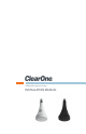
Ceiling Microphone Array INSTALLATION MANUAL
Table of Contents INTRODUCTION...................................................................................................... 1 Product Overview............................................................................................................1 Device Application..........................................................................................................1 INSTALLATION.......................................................................................................
Introduction PRODUCT OVERVIEW The ClearOne Ceiling Microphone Array enhances any conferencing application which demands high-quality audio. The Ceiling Microphone Array is easily installed and combines affordability with exceptional audio quality. The Ceiling Microphone Array features three microphones that are mounted together into a single unit array, providing the rich sound of three individual unidirectional microphones while maintaining full 360 degree coverage.
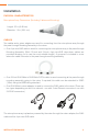
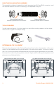
Installation PHYSICAL CHARACTERISTICS Microphone Array Dimensions (Excluding Cables and Mounting) Length: 3.3 in (8.38 cm) Diameter: 1.5 in (3.81 cm) CABLES Two cables and a mixer adapter are used for connecting from the microphone array through the pass-through Mounting Assembly to the mixer. • One 4-pin mini-XLR cable is used for connecting the microphone array to the pass-through Mounting Assembly.
PASS-THROUGH MOUNTING ASSEMBLY This assembly includes a threaded body with integrated mini-XLR and RJ45 connectors, and the required washers and nuts for fastening in a suspended ceiling tile. Microphone Array End Includes 4-pin Mini-XLR Connector Cable to Mixer End Includes Female RJ45 Connector TOOLS REQUIRED You will need a drill and a 1-inch hole saw bit to install the mounting adapter, and an adjustable wrench to tighten the adapter fittings.
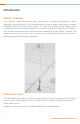
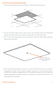
INSTALLING THE MICROPHONE ARRAY 1. Drop the ceiling tile where you have selected to install the microphone array. 2. Run the 25-ft RJ45 cable from the mixer location into the space above the suspended ceiling and down through the opening of the removed tile to conceal the cable. 3. Drill a 1-inch hole through each removed ceiling tile where the pass-through Mounting Assembly will be placed. Drill 1-Inch Hole for Placement of Mounting Assembly 4.
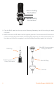
Above Ceiling Tile Surface Below Ceiling Tile Surface 5. Plug the RJ45 cable into the top end of Mounting Assembly, then lift the ceiling tile back into place. 6. Make sure the mini-XLR cable is fed through the grommet. Connect the mini-XLR connector into the receiving plug at the bottom of the Mounting Assembly, then slide the Grommet over the cable and connector snugging it over the Mounting Assembly against the ceiling tile.
7. Attach the Microphone Array to the hanging end of the mini-XLR cable. 8. Connect the RJ45 Male to Mixer adapter cable for your mixer: The Converge Pro requires the RJ45 to mini-Phoenix adapter cable. The RJ45 to XLR-M adapter is for the Interact Pro and Interact AT mixers. 9. Connect the CAT5e cable from the Ceiling Microphone Array to the adapter cable ordered to match the microphone inputs on the mixer.
Software Setup of the Ceiling Microphone Array The Ceiling Microphone Array can be used with the ClearOne Converge Pro, Interact Pro, and Interact AT audio conferencing mixers. Each Ceiling Microphone Array requires 3 microphone inputs. Attention Installers: You must apply the software setup and filter settings in the audio conferencing mixer to obtain the best performance from the ClearOne Ceiling Microphone Array. Failure to apply these filter settings will result in degraded audio performance.
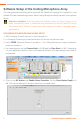
6. Click on the Filter Tab. 7. Add 3 filters Filter 1 is a PEQ filter with the center frequency at 100 Hz with a gain of 5 dB and a Q of 0.40 Filter 2 is a PEQ filter with the center frequency at 4000 Hz with a gain of -2 dB and a Q of 0.27 Filter 3 is a Low Pass filter set at 12000 Hz 8. Other settings in the microphone channel can be set or adjusted based on your application. 9. Repeat these steps for the other Ceiling Microphone Array inputs.
INTERACT PRO MICROPHONE ARRAY SETUP 1. With the Interact software connect to the Interact Pro. 2. In the Interact Software go to the Mic Settings screen 3. Verify P Pwr (Phantom Power) is turned on. The Ceiling Microphone Array requires phantom power for operation. 4. As a starting point set the Coarse Gain to 49 dB and the Fine Gain to 1 dB. Depending on your application and the user to microphone distance, the gain settings may need to be adjusted. 5. Click on the Processing Tab. 6.
9. Other settings in the Microphone Settings screen can be set or adjusted based on your application. 10. Repeat the filter setup for the other 2 Ceiling Microphone Array inputs.
INTERACT AT MICROPHONE ARRAY SETUP 1. With the Interact software connect to the Interact AT. 2. In the Interact Software go to the Mic Settings screen 3. Verify P Pwr (Phantom Power) is turned on. The Ceiling Microphone Array requires phantom power for operation. 4. As a starting point set the Coarse Gain to 49 dB and the Fine Gain to 1 dB. Depending on your application and the user to microphone distance, the gain settings may need to be adjusted. 5. Click on the Processing Tab. 6.
9. Other settings in the Microphone Settings screen can be set or adjusted based on your application. 10. Repeat the filter setup for the other 2 Ceiling Microphone Array inputs.
Compliance COMPLIANCE OVERVIEW ROHS COMPLIANCE All components and processes used to produce the Ceiling Microphone Array will comply with the RoHS initiative. SUSTAINABILITY The Ceiling Microphone Array is compliant with the WEEE recycling initiative. It is made from easily recyclable materials such as aluminum and steel.
Service and Support If you need assistance setting up or operating your product, please contact us. We welcome your comments so we can continue to improve our products and better meet your needs. Technical Support Telephone: 1.800.283.5936 E-mail: tech.support@ClearOne.com Web site: www.ClearOne.com, www.NetStreams.com Sales Telephone: 1.800.707.6994 E-mail: sales@ClearOne.com Techsales Telephone: E-mail: 1.800.705.2103 techsales@ClearOne.
Ceiling Microphone Array Installation Manual ClearOne Document 800-001-013 - Jan. 9, 2012 (Rev. 1.3) © 2012 ClearOne All rights reserved. No part of this document may be reproduced in any form or by any means without written permission from ClearOne. ClearOne reserves specific privileges. Information in this document is subject to change without notice.
ClearOne 5225 Wiley Post Way Suite 500 Salt Lake City, UT 84116 Telephone 1.800.283.5936 1.801.974.3760 1.801.974.3669 FAX E-mail tech.support@clearone.com On the Web www.clearone.