
Instruction Manual


DigiLinX Installation and Design Guide
11-4
All specifications subject to change without notification. All rights reserved. Copyright © 2008 NetStream
Main +1 512.977-9393 / fax +1 512.977.9398 / Toll Free Technical Support +1 866-353-3496
3600 W. Parmer Lane, Suite 100; Austin, TX 78727 / www.netstreams.com.
DoorLinX installations can include the following components:
DoorLinX mounting bracket (DXB100)
DoorLinX electronics package (DX100)
DoorLinX faceplate and doorbell (DXF100-B brushed brass, DXF100-N brushed
nickel, or DXF100-O venetian bronze)
screws (provided)
wood screws (not provided).
Connecting with DigiLinX
DoorLinX works with the following DigiLinX components: PowerLinX, SwitchLinX,
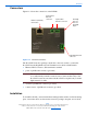
SpeakerLinX, and TouchLinX. Figure 11-3 shows DoorLinX and the relevant
DigiLinX components, including an optional camera.
Figure 11-3 DoorLinX and DigiLinX components
DoorLinX connects to the DigiLinX network like most DigiLinX networked devices
using CAT5 cable and speaker wire (for power). Be sure to run the cables through the
mounting bracket and doorbell mounting plate. To connect DoorLinX, complete the
following steps:
1. Connect a CAT5 cable from the SwitchLinX to the ETHERNET port on the Door-
LinX. If a TouchLinX is nearby, you can connect the CAT5 and power cables to it
from the DoorLinX instead of to the SwitchLinX and PowerLinX.
2. Connect a 16/4 or 14/4 cable from the PowerLinX to the DoorLinX POWER port.