
Manual


Configuring Standalone Installations
3-3
All specifications subject to change without notification. All rights reserved. Copyright © 2006 NetStreams
Main +1 512.977-9393 / fax +1 512.977.9398 / Toll Free Technical Support +1 866-353-3496
3600 W. Parmer Lane, Suite 100; Austin, TX 78727 / www.netstreams.com.
If you want to distribute the video to more than six displays, you can connect two or
more PAN6400 VDCs in cascade mode as discussed in Adding Additional Displays
(Cascade Mode) on page 3-7.
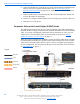
Since Panorama is being configured as a standalone system, the VP700s are highly
recommended. The IR Receiver (included with the VP700) permits control and
switching of the sources using the Panorama remote or a universal remote control. The
IR Emitters allow Panorama to control the display and source. Figure 3-2 shows a
complete wiring diagram for this configuration. For more detail on the ports on the rear
panel of the Panorama, see PAN6400 VDC on page 2-3.
Figure 3-2 Component video
To connect this component video configuration, complete the following steps:
1. Ensure power is off to all devices.
2. Connect the component cable from the component video out ports of the source to
the PAN6400 VDC source IN ports for that source. Match the jacks to the
appropriate PbPrY color-coded ports.
3. Connect an IR Emitter to the PAN6400 VDC IR OUTPUT port for the
corresponding source and place the emitter end over the IR window on the front of
the source.
Display
IR
Receiver
Front
Back
PAN6400
IR
Emitter
Source
w
e
r
t
y
u
PANVP700
L
egen
d
IR Emitter
CAT5
Component