Titan™ Media Cart Installation and Operation Manual
Table of Contents INTRODUCTION SERVICE AND SUPPORT.......................................................................................... 1 PRODUCT RETURNS................................................................................................ 1 UNPACKING............................................................................................................... 1 TITAN SINGLE MEDIA CART.....................................................................................
Introduction The Titan™ Media Carts provide superior strength, mobility and storage space. They are a perfect blend of heavy duty construction and professional styling. Our durable metal carts are an attractive, highly functional addition to any conferencing environment. The ability to hold one screen (single cart) or two screens (dual cart) makes Titan perfect for large conference rooms or distance learning facilities. See the Specifications section on page 12 for maximum screen sizes.
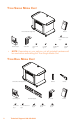
Titan Single Media Cart Universal Base with Support Top Manual 8-32 Pan Head Screws Qty: 2 SHE Vertical Support »» Codec Shelf 1/4-20 Screw Qty: 1 5/16 Bolts Qty: 20 5/16 Washers Qty: 12 5/16 Nuts Qty: 12 NOTE: Depending on your options, not all included hardware will be used when assembling the Titan Single Media Cart.
Before You Begin Before you begin assembling your Titan Media Cart, be sure to have the following: • OmniMount 1N1-L screen mount (single screen configuration) or OmniMount VB150F (X2) screen mounts (dual screen configuration) • 1/2” wrench • Socket wrench with 1/2” socket • Phillips screw driver The Titan Media Carts require one mount for each screen that is to be secured to the unit.
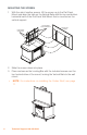
Assembly Titan Single Media Cart ASSEMBLING THE HARDWARE 1. Align the Vertical Support over the self-clinching nuts in the Universal Base. »» NOTE: The self-clinching nuts are attached to the top of the Universal Base. 2. Secure the Vertical Support using six 5/16 Bolts. Bolts Vertical Support Support Top Universal Base 4 Technical Support: 800.283.
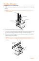
3. »» Remove and set aside the Locking Bar from the OmniMount 1N1-L Flat Panel Mount assembly (not supplied), then securely anchor the mount to the Vertical Support using four 5/16 Bolts, four 5/16 Washers and four 5/16 Nuts. NOTE: The Flat Panel Mount can be attached higher or lower on the Vertical Support depending on desired position and size of screen. Locking Bar and Screws Wall Plate Washers and Nuts Bolts 4.
MOUNTING THE SCREEN 1. With the aid of another person, lift the screen up to the Flat Panel Mount and align the tabs on the Vertical Rails with the top and bottom horizontal bars of the Flat Panel Wall Mount that is mounted on the vertical support. Vertical Rails Over Wall Mount Locking Bar and Screws 2. Slide the screen down into place. 3. Place and secure the Locking Bar with the included screws over the top horizontal bar of the mount, locking the Vertical Rails to the wall mount.
Titan Dual Media Cart ASSEMBLING THE HARDWARE 1. »» Align the Vertical Support over the self-clinching nuts in the Universal Base. NOTE: The self-clinching nuts are attached to the top of the Universal Base. Bolts Vertical Support Support Top Universal Base 2. Secure Vertical Support using six 5/16 Bolts. 3. Line up the Horizontal Support alignment pins with the guiding holes on the Vertical Support at desired height and slide into place. 4.
5. Attach the Rail Track to the Horizontal Support using two 8-32 Pan Head Screws. 6. Slide the Camera Bracket down over rail. »» NOTE: Attaching the Camera Bracket is optional. The bracket is normally used with codecs that have a detachable camera or with a small PTZ camera. This bracket allows the camera to be placed at eye-level between the monitors. Camera Shelf Pan Head Screws Rail Track Horizontal Support »» 7.
8. »» Using hardware supplied with the Wall Mount, attach the Vertical Rails with the Rubber Stops to the back of the screen. (See OmniMount VB150F instructions for more information.) NOTE: Titan Media Carts require one OmniMount VB150F Wall Mount (not supplied) for each screen that is to be secured to the support. Rubber Stop Vertical Rails Rubber Stop MOUNTING THE SCREENS 1.
2. Lower the screen into place with the Vertical Rails hooking over the Wall Plate. 3. Thread the Locking Bar from the side through the Wall Plate and both Vertical Rails. When fully inserted, turn in place to position locking tab.. »» NOTE: For instructions on installing the Codec Shelf, please see page 11. Attaching a PTZ Camera 1. Secure the camera to Camera Bracket using the 1/4-20 Screw.
Attaching the Codec Shelf »» 1. NOTE: The Codec Shelf supports a set-top codec or PTZ camera; using the shelf is optional. Align the Codec Shelf with the guiding holes on the Vertical Support. Codec Shelf Washer and Nut Support Top (Screen Mounting Hardware Not Shown.) 2. »» Secure the Codec Shelf to Vertical Support using the attached bolts on Vertical Support, four 5/16 Washers, and four 5/16 Nuts.
Appendix Specifications Dimensions (W x H x D) 45” x 31” x 28” Assembled Dimensions without screens (W x H x D) Single: 45” x 72” x 28” Dual: 72” x 72” x 28” Integrated Rack Height: 9 space, 15.75” (40 cm) Depth: 22” Rack rails: included Rail recess: 2” clearance from door Casters Heavy duty (250 lb.
Appendix 13