MAX™ Wireless INSTALLATION & OPERATION MANUAL
TECHNICAL SUPPORT Telephone: Fax: Email: Web: 1-800-283-5936 (USA) or 1-801-974-3760 1-801-977-0087 tech.support@clearone.com www.clearone.com MAX WIRELESS INSTALLATION & OPERATION MANUAL CLEARONE PART NO. 800-158-001 SEPTEMBER 2007 (REV 4.0) U.S. PATENT NO. D499,392. OTHER PATENTS PENDING. © 2007 ClearOne Communications, Inc. All rights reserved. No part of this document may be reproduced in any form or by any means without written permission from ClearOne Communications.
TABLE OF CONTENTS CHAPTER 1: INTRODUCTION Service And Support Product Returns Unpacking Safety Information CHAPTER 2: GETTING STARTED Connecting MAX Wireless to an Analog Phone Line Connecting MAX Wireless to a Digital (PBX) Line Using Your MAX Wireless Phone CHAPTER 3: USER OPTIONS Calling Features Programming Features Alert Tones CHAPTER 4: MAXATTACH WIRELESS Using the MAXAttach Wireless Conferencing System CHAPTER 5: MAINTENANCE Caring For MAX Wireless Phones Electrical Considerations Troubleshootin
CHAPTER 1: INTRODUCTION Thank you for purchasing the ClearOne® MAX™ Wireless conferencing telephone. MAX™ Wireless is ideal for small conference rooms with up to eight participants, and provides the convenience of wireless without compromising audio quality or call security. MAX Wireless uses the WDCT (Worldwide Digital Cordless Telecommunications) standard, which ensures reliability, stability, and excellent sound quality.
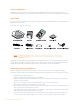
PRODUCT RETURNS All product returns require a return materials authorization (RMA) number. Please contact ClearOne Technical Support before attempting to return your product. Make sure you return all the items that shipped with your product. UNPACKING Ensure you have received all items shown below. After unpacking, place the MAX Wireless Conferencing Pod and Base Unit on a level surface.
• Do not overload wall outlets and extension cords as this can result in the risk of fire or electric shock. • Never push objects of any kind into this product through cabinet slots as they may touch dangerous voltage points or short out parts that could result in fire or electric shock. • Never spill liquids on the product. • To reduce the risk of electric shock, do not disassemble this product. Opening or removing covers may expose you to dangerous voltages or other risks.
• Do not store this product or the battery pack in a high temperature area. When exposed to low temperatures, the battery pack should be stabilized at room temperature before use. • Your battery pack is rechargeable and can be recycled once it outlives its usefulness. Depending upon your local and state law, it might be illegal to dispose of this battery into a municipal waste system. Check with your local solid waste company for more information on your recycling options for the battery pack.
CHAPTER 2: GETTING STARTED CONNECTING MAX WIRELESS TO AN ANALOG PHONE LINE 1. Slide the cover off of the battery compartment on the bottom of the pod (as shown on left below). 2. Connect the battery pack plug into the port in the compartment, insert the battery pack, and slide the cover back into place (as shown on right above). CAUTION: Use only the battery pack that came with this unit. Replace only with the same battery type as recommended by manufacturer.
5. Connect a recording device to the 2.5 mm mono audio jack (optional).
CONNECTING MAX WIRELESS TO A DIGITAL (PBX) PHONE LINE MAX Wireless phones can be connected to a PBX by using a digital-to-analog converter. To connect a MAX Wireless phone to a digital (PBX) line, use the following diagram and procedure: 1. Connect the telephone cable to the phone jack on the back of the base unit, and the other end into the digital-to-analog converter. 2. Connect the converter's AC power adapter to an electrical outlet. 3.
USING YOUR MAX WIRELESS PHONE To Make a Call 1. Press the ON/OFF key. You will hear a dial tone. 2. Dial the number as you would on a standard phone. The number is displayed on the LCD screen. NOTE: You can also pre-dial the number while in standby (inactive) mode and press the ON/OFF key to connect the call. Press and hold the pound key (#) to enter a pause in the dialing string.
To Mute a Call • Press MUTE to mute the call. • Press MUTE again to un-mute the call. To Make a Call Using the Phonebook 1. Press the ON/OFF key. You will hear a dial tone. 2. Press PHONEBOOK. 3. Press the number key (0-9) that corresponds with the location of the stored phone number you want to dial. This feature must be programmed before use. See Programming Features for additional information. To Store a Number In the Phonebook 1.
CHAPTER 3: USER OPTIONS CALLING FEATURES In addition to the basic phone operations described in the previous chapter, you can use calling features to perform any of the following functions during a call: • • • • • Change to Pulse Dialing Send a Flash Signal Display a Phone Number Adjust Speaker Volume Turn the Ringer On/Off. These functions are described in the following sections. To Use Pulse Dialing MAX Wireless uses tone dialing by default. You can temporarily change to pulse dialing during a call.
PROGRAMMING FEATURES To allow for individual preferences and enhanced usability, MAX Wireless provides the following programmable features: • • • • • • • Ringer Melody Dialing Mode Flash Duration Local Phone Number Speed Dial Numbers Service Center Number AGC/ALC (Automatic Gain Control/Automatic Level Control) You may also restore factory defaults. The following sections describe how to program these features. Entering Programming Mode 1.
3. 4. 5. 6. Press REDIAL/PROG. Enter the local phone number. Press REDIAL/PROG to save the number. Press CLEAR to exit programming mode. NOTE: Press and hold the 1 numeric key to enter a hyphen. Press the “*” key to enter a space in the number. Use CLEAR to delete the old number before entering a new number. To Program a Speed Dial Number 1. 2. 3. 4. 5. 6. Press and hold REDIAL/PROG until the program icon appears on the LCD screen. Press the 5 numeric key to enter the speed dial menu. Press REDIAL/PROG.
ALERT TONES The table below describes alert tones used by MAX Wireless.
CHAPTER 4: MAXATTACH WIRELESS USING THE MAXATTACH WIRELESS CONFERENCING SYSTEM MAXAttach™ Wireless is a dual-pod conferencing system. The MAXAttach™ Wireless pods function only with their associated base unit. The base unit and conferencing pods are programmed at the factory, and they have matching serial numbers. The serial number is located on the back of the base unit, and on the bottom of each pod.
CHAPTER 5: MAINTENANCE CARING FOR MAX WIRELESS PHONES • Follow all warnings and instructions marked on your MAX Wireless phone. • Unplug base unit and conferencing pod from the wall outlet before cleaning. • Use a damp cloth moistened with water to clean the outside of your conferencing pod or base unit and power supply. Do not use liquid or aerosol cleaners. ELECTRICAL CONSIDERATIONS • Use only the power adapter that comes with your conferencing phone.
Troubleshooting Table Use the table below to troubleshoot your MAX Wireless system: 16 Technical Services: 800-283-5936
APPENDIX SPECIFICATIONS Dimensions (W X D X H) Phone section: 10.5" x 10.5" x 3" (26.7 cm x 26.7 cm x 7.6 cm) Base unit: 4.25" x 5.5" x 2.5" (10.8 cm x 14 cm x 6.4 cm) Weight Phone section: 2.7 lb. (1.2 kg) Base unit: .6 lb. (0.27 kg) Shipping: 10 lb. (4.5 kg) Environmental Operating Temperature: 32–118° F (0–48° C) Storage temperature: 41–158° F (5–70° C) Operating Humidity: 15 to 80% Storage humidity: 10 to 90% Power Pod: Custom battery pack with nickel metal hydride batteries, 7.
COMPLIANCE FCC Part 15/ICES-003 Compliance This equipment has been tested and found to comply with the limits for a Class A digital device, pursuant to Part 15 of the FCC rules and Industry Canada ICES-003. These limits are designed to provide reasonable protection against harmful interference when the equipment is operated in a commercial environment.
If you experience problems with this equipment, contact ClearOne Communications, 5225 Wiley Post Way, Salt Lake City, Utah 84116, or by phone at (801) 975-7200 for repair and warranty information. If the trouble is causing harm to the telephone network, the telephone company may request you remove the equipment from the network until the problem is resolved. No user serviceable parts are contained in this product.
European Compliance Conformity of the equipment with the guidelines below is attested by the CE mark. EC Declaration of Conformity Manufacturer’s Name: ClearOne Communications Manufacturer’s Address: Edgewater Corporate Park South Tower 5225 Wiley Post Way, Suite 500 Salt Lake City, Utah 84116 U.S.A. EU Representative Name: ClearOne Communications Ltd. EU Representative Address: Atlantic House Imperial Way Reading Berkshire RG2 OTD United Kingdom Model: MAX Wireless, MAXAttach Wireless.
Safety - 73/23/EEC “Low Voltage Directive (LVD)”: IEC 60950-1: 2001 Safety of Information Technology Equipment, Including Electrical Business Equipment.