
User's Manual


Venture-Base Installation and Operations Manual Page 5
Technical or Setup Assistance • Telephone: 800.945.7730 (USA)
801.975.7200 (worldwide) • Worldwide Web @ http://www.gentner.com
4. Tone. This switch sends a 40Hz test tone
through the audio circuit to test the transmitter and
aid in tuning receivers. To tune receivers, set the
transmitter to the desired operating channel,
activate the tone, then tune the receiver for clearest
reception. (Refer to receiver user’s guide.)
5. Hi Pass. This switch activates the high-pass
filter, which rolls off low frequencies below 180Hz
(i.e., wind noise and room reverberation). These
low frequencies are not needed for voice
intelligibility.
6. Unbalanced. This unbalanced RCA audio input
jack is a 10 kOhm input intended for connection of
unbalanced signals from line/speaker-level outputs.
7. Input Select. This screwdriver-set control selects
the input source from balanced mic and line-level
signals to unbalanced line and speaker-level signals.
8. Ballanced Input. The balanced audio input XLR
connector is 600 Ohms, transformer balanced, for
balanced mic and line level-input signals.
9. Power. The Venture-Base requires 11–15Vdc
a500mA, supplied by the provided AC power
supply, or by other sources (batteries, auto cigarette
lighter).
The Venture-Base is designed for easy installation
and setup. To install the Venture-Base, follow these
step-by-step instructions:
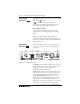
Step 1 — Antenna Connection
Attach the provided rubber whip antenna to the
modified TNC connector [1] (Figure 2, Page 4).
It may be installed directly on the rear of the
Venture-Base, or remotely mounted on the
supplied antenna mount and 49-foot cable
(Figure 3, below).
Unless the transmitter is used in a very small
room, best performance is with the remote
antenna placed away from the Venture-Base,
but as close to the receiver(s) as possible.
Installation