
User's Manual


Page 4 Venture-Base Installation and Operations Manual
Technical or Setup Assistance • Telephone: 800.945.7730 (USA)
801.975.7200 (worldwide) • Worldwide Web @ http://www.gentner.com
7. Monitor Level. This control sets the level of the
audio at the jack [8].
8. . This headphone jack provides easy
monitoring of transmitter operation. Its output is
1W, capable of driving most headphones.
HEADPHONE NOTE:
Ensure that the headphone jack does not make
metal contact with the face place of the Venture-
Base.
9. RF. This LED indicates proper RF-circuit
function to simplify system troubleshooting (i.e. no
signal being received). When lit, the LED indicates
RF signal presence.
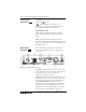
The Venture-Base’s back-panel connectors and
controls (See Figure 2, below.) are designed for
ease in use.
Front Panel
Continued
Back Panel
Controls
1. Antenna. This 50 Ohm output is for connection
of the supplied local antenna or the remote antenna
(see Step 1, Page 6). Do not operate the
transmitter without the antenna.
2. RF Level. This switch sets the RF output to one-
quarter, half or full power to control the amount of
coverage and to reduce the chance of interference.
3. RF Channel Switch. RF channels can be
changed by setting the thumbwheel to any channel
from 01–19. The corresponding frequencies are
indicated on the top of the transmitter. If set other
than 01–19, the system defaults to channel 01.
Figure 2. TX-37A back panel controls