VIEW® Pro - D110 Digital AV Decoder Installation and Users Manual
ClearOne 5225 Wiley Post Way Suite 500 Salt Lake City, UT 84116 Telephone 1.800.283.5936 1.801.974.3760 FAX 1.801.303.5711 E-mail On the Web tech.support@clearone.com www.clearone.com VIEW Pro D110 Installation Manual ClearOne Document DOC-0146-001 - October, 2014 (Rev. 1.0) © 2014 ClearOne All rights reserved. No part of this document may be reproduced in any form or by any means without written permission from ClearOne. ClearOne reserves specific privileges.
Table of Contents INTRODUCTION...............................................................................................................................................................1 PRODUCT OVERVIEW...................................................................................................................................................1 StreamNet AVoIP™ VIDEO PLATFORM.............................................................................................................................
VIEW PRO RS-232 CONTROL..................................................................................................................................15 LUA FILE DRIVER TEMPLATES...........................................................................................................................................15 PREPARING THE NEW ONE-WAY RS-232 DRIVER FILES..................................................................................................15 PREPARING THE ENCODER/DECODER..............
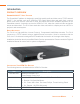
Introduction PRODUCT OVERVIEW StreamNet AVoIP™ Video Platform The StreamNet IP platform is designed to send high-quality audio and video over a TCP/IP network (AVoIP™). An encoder, such as a VIEW Pro E120, takes digital video and audio from a source device, such as a receiver, cable box or DVR, and makes the source available anywhere on the StreamNet network. A decoder, such as the VIEW Pro D110, takes the combined video and audio stream and decodes it.
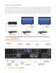
Connections The VIEW Pro D110 decoder has connectors as described below. • 1x - IR Input connector compatible with StreamNet IR sensor (3.5mm) • 1x - IR Input Receiver window on front panel • 1x - IR Output connector compatible with StreamNet IR emitter (3.5mm) • 1x - Balanced Audio Output (Modular Phoenix-type connector, left and right) • 1x - Stereo 3.5mm Barrel Plug (Line Level) Input (Currently not used) • 1x - Stereo 3.5mm Barrel Plug (Line Level) Output • 1x - HDMI output connector.
IR In This jack allows connection of an optional infrared receiver. The infrared receiver can pick up IR remote control signals. Port is also for IR Learning and IR Network pass-through. IR Out This jack allows connection of an optional infrared transmitter. The infrared transmitter can send IR remote control signals. RS -232 (COM) These jacks allow the D110 to control other connected devices. It supports sending RS-232 commands to control devices.
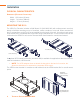
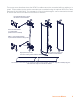
Installation PHYSICAL CHARACTERISTICS Dimensions (Excluding Connectors) Width: 12.2 inches (310mm) Length: 7.4 inches (188mm) Height: 1.75 inch (44.4mm) MOUNTING THE D110 The VIEW Pro Decoder includes a Wall Mount Kit (910-0002-002) with surface-mount ears that attach to facilitate mounting on top of a surface, under a surface or on a wall. When mounted, all the I/O connections on the D110 are accessible from theMounting back of the unit.
There may some situations where the VIEW Pro cables cannot be concealed within a cabinet or in a wall. These cables can be surface mounted and concealed using the optional VIEW Pro Cable Raceway Kit (910-0002-003). This raceway, in 12-inch joinable lengths, can be mounted to the wall to secure and secure the cables to the VIEW Pro devices. Use included wire ties to secure the cables to the wall bracket Mount the wall brackets to a solid surface.
THE D110 IN A NETWORK An E120 Encoder receives input from an AV Source Device such as BluRay Player or DVD Player, then distributes it over a TCP/IP network using a standard 100 Mbit or gigabit Ethernet connection. The D110 Decoders, as counterparts, are installed at the locations of the target video displays. They operate together: the Encoder providing the IP data for the Decoders to deliver to the display.
Software Setup of the D110 The D110 is setup for use in the commercial or residential network using the StreamNet Dealer Setup program and the accompanying StreamNet Dealer Setup manual. StreamNet Dealer Setup is a PC-based program that allows you to configure devices so that they can communicate across a StreamNet network.
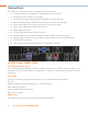
D110 SCREENS IN THE DEALER SETUP PROGRAM Verify the configuration information on the tabs for the D110 device as shown in the following screen examples: Adding an D110 to a Project 1. Enter the following information: Device Name - Edit to name the D110 Device. Model Number - Select the D110 Device. 2. Enter the following information: GPIO Name - This is mainly used in macros By default this receives the Device Name. Room Name - This is to conveniently identify the room the decoder is in your project.
3. Select Save & Continue 4. Complete the information for each D110 in your project. Info Tab Current IP Address - The current IP address of the D110. Current Subnet Mask - The current subnet mask of the D110. Device Type - The type of device that this is. Model Number - The D110 model number. Firmware Version - What firmware version is currently running on the D110. Device Name - Descriptive name assigned to the device when creating the project. Serial Number - Displays the D110 serial number.
SHOW ADVANCED OPTIONS Advanced options can be accessed by clicking on the Show Advanced Options button in the lower portion of the Info Tab screen. Enable Static IP Address - Checking the check box allows entry of an IP address for the decoder. Enable DHCP - Checking the check box allows the decoder IP Address to be assigned by a DHCP Server. Network Subnet Mask - Allows setting the subnet for the decoder. Gateway IP - Allows setting a specific gateway node to serve as an access point to another network.
Display Outputs Tab Room Name - Select the room name for the decoder. Display Control Driver - Select the device driver (.lua file) used to control the display. IR appears as the default supporting an Infrared remote, appears as the default. »» NOTE: A replacement .lua file can be created from a template that will allow customizing the VIEW Pro encoder/decoder to receive RS-232 commands instead of IR.
Display Controls Tab This screen allows you to enter a label, which will appear in the GUI, and associate it with a macro. Building macros is discussed in Chapter 11 of the Dealer Setup manual. 12 Technical Support: 800.283.
IR Tab The IR tab allows you to configure how the VIEW Pro responds when it receives a source or macro IR command. By default, it is configured to allow IR pass through the network to the currently selected source. Network IR must be disabled if you do not want IR to pass from the selected VIEW Pro.
GPIO Tab This tab allows you to choose a macro associated with each input state: High/Open and Low/ Closed. The VIEW Pro macros are created and used in the same manner as the VIEW legacy products. Refer to the Dealer Setup Manual, Chapter 11 Section 1 (11-1) for the “Favorites section,” which explains macros in detail. The GPIO Tab contains six GPIO components (3x Input Triggers and 3x Relays).
VIEW Pro RS-232 Control The VIEW Pro has two DB9 Serial ports available on both Encoder and Decoder. The function and operation of the ports is defined in a .lua file used as a driver and implemented through StreamNet Dealer Setup. These ports communicate RS-232 commands and can be used in the following scenarios: 1. Input and/or Output Control. 2. Source Control. 3. Display Control The VIEW Pro .
For Example: If you are creating a one way RS-232 file for a DVD you would: • Locate the Driver Template directory (i.e. C:\Program Files (x86)\ClearOne\StreamNet Application Suite\viewPro\drivers) • Copy the DVDTEMPLATE.LUA file into the Drivers folder that you created • Rename the DVDTEMPLATE.LUA 16 In this example, we will call it TESTDVD.LUA Technical Support: 800.283.
PREPARING THE ENCODER/DECODER The next step is to configure the Encoder/Decoder device. Add the Encoder/Decoder as you normally would. Do NOT choose a source type that is tied to a specific manufacturer or product model. If you are in doubt choose the source type you would use if this were and IR device. For this example, we would choose DVD.
Once the device is added select the Sources tab for the Encoder/Decoder. Change the Driver file from IR to your newly created driver. For this example, we would change the driver file from IR to DVDTemplate.lua. Now Apply your changes. The Encoder/Decoder is now configured to use your one-way Driver file. So far all you have applied is a renamed file. Now you need to modify the driver file to support your source.
In the RS-232 Protocol section of the .lua file, locate the communication settings. Normally these settings will include: Baud rate, Data Bit, Stop Bit, and Parity. Once you find them you will need to verify that these commands match those used in the driver file.
Verify that the baud, bits, parity, and stop values in the driver file match the settings listed in the RS232 Protocol. Most devices use Baud=9600, Data bits=8, Parity=0, and Stop bits=1. Now locate the Command table in the driver file. Do a text search for: local CmdTable = 20 Technical Support: 800.283.
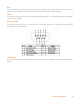
Below the local CmdTable = text are the available commands where you can enter RS-232 commands. For each command you will enter the command between the quotation marks. For example: To enter the RS-232 command for TUNE UP: Locate the TUNE UP command line: [‘TUNE UP’] = “”, Add the appropriate RS-232 command for the source to do a TUNE UP between the quotes [‘TUNE UP’] = “W 1 6 1”, Note that in most RS-232 Protocols you are required to put a Carriage Return to indicate an end of command.
Your table should begin looking like this: Once you have completed your changes, save the file. From Dealer Setup, send the configuration to your Encoder/Decoder. The StreamNet GUI will now send the RS-232 command to the source via the DB9 port instead of the IR. 22 Technical Support: 800.283.
VIEW Pro and VIEW Legacy Interoperability There are several types of interoperability with VIEW Pro and the legacy VIEW products: • Control Sharing • Audio Streaming Interoperability • IR Learning and Control • Firmware Upgrading CONTROL SHARING From a command and control standpoint, VIEW legacy and VIEW Pro devices all appear and act the same; that is, a TouchLinX Touch Panel, Virtual Control, and VIEW Virtual Matrix (VVM) can all be used to control both types of products.
IR LEARNING AND CONTROL The accessory kits for the IR Emitter and IR Receiver allow the use of these devices with the VIEW Pro products. For example, an IR Emitter can be placed over the integrated IR Receiver of a display so signals from the VIEW Pro can be used to control the display. An IR Receiver unit can be used to receive and relay IR commands to a device placed out of the line of sight of the IR control device.
VIEW Pro Accessory Kits KIT DESCRIPTIONS The following accessory kits are available to meet the mounting and control needs of your VIEW Pro Encoders and Decoders: Part Number 910-0002-001 910-0002-002 910-0002-003 Kit Name VIEW Pro Rack Mount Description Rack Mount Kit for VIEW Pro Encoder E120, Decoder D110 (Included with Encoder) • 6X - Screw, M3 x 6mm, Pan-head, Philips, Thread Locking, Black VIEW Pro Wall Mount Wall Mount Kit for VIEW Pro Encoder E120, Decoder D110 (Included with Decoder) • 2X
Compliance COMPLIANCE OVERVIEW RoHS Compliance All components and processes used to produce the D110 will comply with the RoHS initiative. Sustainability The D110 is compliant with the WEEE recycling initiative. It is made from easily recyclable materials such as aluminum and steel. ELECTRICAL SAFETY ADVISORY This equipment uses DC power supplied from an external source which can be subjected to electrical surges, typically lightning transients which are very destructive to customer terminal equipment.
Service and Support If you need assistance setting up or operating your product, please contact us. We welcome your comments so we can continue to improve our products and better meet your needs. TECHNICAL SUPPORT Telephone: 1.800.283.5936 E-mail: tech.support@ClearOne.com Web site: www.ClearOne.com SALES Telephone: 1.800.707.6994 E-mail: sales@ClearOne.com TECHSALES Telephone: 1.800.705.2103 E-mail: techsales@ClearOne.