Wood Plasma Cart Conferencing Furniture INSTALLATION & OPERATION MANUAL
TABLE OF CONTENTS INTRODUCTION . . . . . . . . . . . . . . . . . . . . . . . . . . . . . . . . . . . . . . . . . . . . . . . . . . . . . . . . . . . 1 Service and Support. . . . . . . . . . . . . . . . . . . . . . . . . . . . . . . . . . . . . . . . . . . . . . . . . . . . . . . . 1 Product Returns . . . . . . . . . . . . . . . . . . . . . . . . . . . . . . . . . . . . . . . . . . . . . . . . . . . . . . . . . . . 1 Unpacking . . . . . . . . . . . . . . . . . . . . . . . . . . . . . . . . . . . . . . . .
INTRODUCTION ClearOne’s Wood Plasma Carts provide superior strength, mobility and storage space. They are a perfect blend of heavy duty construction and professional styling. Our durable wood carts are an attractive, highly functional addition to any conferencing environment. The ability to hold one plasma screen (single cart) or two plasma screens (dual cart) makes ClearOne wood carts perfect for large conference rooms or distance learning facilities.
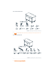
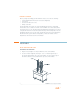
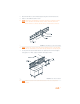
WOOD SINGLE PLASMA CART FIGURE 1.1 Unpacking the Wood Single Plasma Cart » NOTE: Not all hardware will be used when assembling the Wood Single Plasma Cart. WOOD DUAL PLASMA CART FIGURE 1.2 Unpacking the Wood Dual Plasma Cart 2 Furniture Service Department: 800.283.
BEFORE YOU BEGIN Before you begin assembling your Wood Plasma Cart, be sure to have the following: • • • • Chief PST-XXXX plasma mount (two for the dual configuration) 5/16" wrench Socket wrench with 5/16" socket Phillips screw driver The Wood Plasma Carts require one Chief PST-XXXX plasma mount for each plasma monitor that is to be secured to the unit.
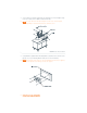
3. Securely anchor the plasma Static Mount (not supplied) to the Vertical Support using four 5/16 ¾” Bolts, four 5/16 Washers and four 5/16 Nuts. » NOTE: The Static Mount can be attached higher or lower on the Vertical Support depending on desired position and size of plasma screen. FIGURE 2.2 Static Mount Installation 4. Using hardware supplied with the Mounting Bracket, attach bracket to the back of the plasma screen. (See Mounting Bracket instructions for more information.
MOUNTING A PLASMA SCREEN » NOTE: Before attempting to place a plasma screen on the mount, make sure the Safety Flag on the Static Mount is lowered to the side. 1. With the aid of another person, lift the plasma screen up to the Static Mount and align the mounting buttons on the plasma bracket with the teardrop slots in the Static Mount. FIGURE 2.4 Plasma Screen Installation 2. Slide the plasma screen into place. 3. Raise the Safety Flag to secure the plasma screen.
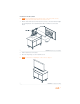
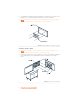
WOOD DUAL PLASMA CART ASSEMBLING THE HARDWARE 1. Align the Vertical Support over the pre-drilled holes in the Universal Base. 2. Secure the Vertical Support by inserting six 5/16 1 ½” Bolts through the top of the Vertical Support and the top of the Universal Base. Secure the bolts using six flat washers and six 5/16 nuts underneath the top of the Universal Base. FIGURE 2.6 Vertical Support Installation 3.
5. Attach the Rail Track to the Horizontal Support using two 8-32 Pan Head Screws. 6. Slide the Camera Bracket down over rail. » NOTE: Attaching the Camera Bracket is optional. The bracket is normally used with codecs that have a detachable camera or with a small PTZ camera. This bracket allows the camera to be placed at eye-level between the monitors. FIGURE 2.
8. Using hardware supplied with the Mounting Bracket, attach bracket to the back of the plasma screen. (See Mounting Bracket instructions for more information.) » NOTE: Wood Plasma Carts require one Chief PST-XXXX plasma mount (not supplied) for each plasma screen that is to be secured to the support. FIGURE 2.
2. Slide the plasma screen into place. 3. Raise the Safety Flag to secure the plasma screen. » NOTE: For instructions on installing the Codec Shelf, please see page 10. FIGURE 2.12 Completed Assembly ATTACHING A PTZ CAMERA 1. Secure the camera to Camera Bracket using the 1/4-20 Screw. » NOTE: Different camera models can be attached to the Camera Bracket using individual mounting hardware supplied by the camera manufacturer. FIGURE 2.
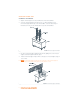
ATTACHING THE CODEC SHELF » Note: The Codec Shelf supports a set-top codec or PTZ camera; using the shelf is optional. 1. Align the Codec Shelf with the guiding holes on the Vertical Support. FIGURE 2.14 Codec Shelf Installation for Single and Dual Carts 2. Secure the Codec Shelf to Vertical Support using the attached bolts on Vertical Support, four 5/16 Washers, and four 5/16 Nuts.
APPENDIX SPECIFICATIONS DIMENSIONS (W X H X D) Width: 47.75" Height: 3.5" Depth: 23.25” ASSEMBLED DIMENSIONS WITHOUT PLASMA SCREENS (W X H X D) Single: 45" x 72" x 28" Dual: 72" x 72" x 28" INTEGRATED RACK Height: 20 space, 17.5" (40 cm) Depth: 18" Rack rails: included Rail recess: 2" clearance from door CASTERS Heavy duty (250 lb.
12 Furniture Service Department: 800.283.