
Specifications


TECHNICAL SUPPORT: 1.800.283.5936 (USA) OR 1.801.974.3760
INSTALLATION AND SETUP • REAR PANEL
5
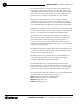
Rear Panel
1. Power
This power module (see Figures 2 and 3) accommodates power
ranging from 100–240VAC, 50/60Hz. The module uses an IEC-type
connector. No switching is required.
2.
Inputs 1-8 These Phoenix block connectors (see Figures 2 and 4) are
for connection of eight mic-level or line-level (selectable) inputs. These
connectors are typically used for mics, but can be configured for use with
VCRs, CD players, XAP TH2, etc. These inputs can be mixed in any gated or
non-gated combination and routed to any of the 12 outputs. Default input
level is -55dBu. For more information about input adjustments, see page
37. For electrical specifications, see Appendix A: Specifications.
3.
RS-485
Remote Panel A/B Port These four-pin Phoenix connector ports
(see Figures 2 and 5) allow you to control the XAP 800 with the Gentner
Control Panel.
Power is supplied through the RS-485 ports to the remote Control Panels
from the XAP 800. This power is limited to a total of 300mA at 15 volts for
each connector. Over-current protection is provided on the +15V pins to
prevent damage in the event of shorting. External power can be provided
to control devices when more current is required. See page 90 for
maximum cable run distances when using Gentner Control Panels.
4. Control/Status P
orts A and B These two female DB25 connectors (see
Figures 2 and 6) are for connecting control devices to the XAP 800. The
control devices have access to the command set for the XAP 800 and can
be used for common functions such as volume control, muting, preset
change, room combining, etc. Devices can be connected to either port.
For instructions on how to program the control and status pins, see the
GPIO section on page 60. The default settings allow control and status of
inputs, outputs, volume, and presets. These pins are active low. The 32
presets can also be activated via these connectors. For pinout and default
information, see Appendix B.
5.
Outputs 1-12 These three-pin Phoenix connectors (see Figures 2, 7, and
8) is for connection of twelve line-level balanced outputs with three-pin
Phoenix connectors. These outputs are typically used for connection to
1
5
2
5
6
7 8
9
4
3
Expansion Bus
In
Out
0A P 8 0
Figure 2. Rear Panel
Figure 3. Power Plug
Figure 4. Inputs 1-8
Figure 5. RS-485 Remote Panel A/B Ports
Figure 6. Control/Status Ports A and B
13
25
1
14