Instruction Manual P1890E/EN 2011-09 17BP…B… Cordless EC Tool For additional product information visit our website at http://www.apextoolgroup.
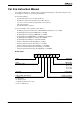
For this Instruction Manual This Instruction Manual is a – translation of the original Instruction Manual – intended for all persons who work with this tool but do not do any programming work. The Instruction Manual • provides important notes for safe and effective use. • describes the function and operation of the cordless EC tool. • serves as a reference work for technical data, service intervals and spare part orders. • provides information on options.
Identification text: 17BP represents all models of the cordless EC tool as described here. PS represents all models of power supply as described here: Accupack / Power Module RF15.4 represents the Wireless Fidelity IEEE 802.15.4 LMC represents the interchangeable memory module LiveWire Memory Chip ➔ refers to required actions. • refers to lists. kursiv refers menu items, i. e.: Diagnostics <…> refers elements, that have to be selected or deselected, such as buttons or control boxes, i. e.
P1890E/EN 2011-09 90a_ Deckblatt en.fm, 26.09.
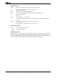
Contents 1 Safety 7 1.1 1.2 1.3 1.4 1.5 1.6 1.7 Warnings and notes.............................................................................. Basic requirements for safe working practices ..................................... Operator training................................................................................... Personal protective equipment ............................................................. Designated use........................................................................
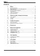
8 Maintenance 39 8.1 8.2 8.3 8.4 Cleaning instructions .......................................................................... Service schedule ................................................................................ Lubricants ........................................................................................... Disassembling gear ............................................................................ 39 39 40 40 9 Troubleshooting 41 10 Spare parts 49 10.1 10.2 10.
Safety 1 Safety 1.1 Warnings and notes Warning notes are identified by a signal word and a pictogram: • The signal word describes the severity and the probability of the impending danger. • The pictogram describes the type of danger. WARNING! Indicates a potentially hazardous situation which, if not avoided, could result in serious injury. 2009-08 CAUTION! Indicates a potentially hazardous situation which, if not avoided, may result in minor or moderate injury or property and environmental damage.
1 Safety 1.2 Basic requirements for safe working practices You should read all instructions. Nonobservance of the instructions below may result in electrical shock, burns and serious injuries. CAUTION! Work area ➔ Ensure there is enough space in the work area. ➔ Keep the work area clean. ➔ Electrical safety ➔ Protect the 17BP from rain and moisture. Use only in the inner zone (IP40). ➔ Follow the safety instructions printed on the battery pack and charger.
Safety 1.5 Designated use The 17BP is designed exclusively for fastening and releasing threaded fasteners. The communication with the controller is allowed only over the following interface ports: • • • • 1.6 Types Communications All IrDA interface port of the tool holder, order no. 935290 17BPR… 868 MHz with base station, order no. 961300 (EU) 17BPX... WLAN standard IEEE 802.11b WEP, WPA/WPA2 17BPY... WLAN standard IEEE 802.11a/b/g WEP, WPA(2), LEAP, PEAP 17BPZ… WPAN standard IEEE 802.15.
2 Scope of supply, transport and storage 2 Scope of supply, transport and storage 2.1 Items supplied Check shipment for transit damage and ensure that all items have been supplied: 1 17BP 1 This instruction manual 1 Declaration of Conformity 1 Factory test certificate for transducers 1 Machine capability analysis 2.2 Transport Transport and store the 17BP in the original packaging. The packaging is recyclable. 2.
Product description 3 Product description 3.1 General description • • • • • • • • • • • • Sturdy, brushless motor with resolver. Shutoff is torque/angle-controlled. LCD display with information on status, torque and angle. Green OK and red NOK LED display provides information on the current fastening result. LED lighting makes it possible to find the screw point quickly. Clockwise/counterclockwise rotation Low vibration level Servo and fastening electronics are integrated in the 17BP.
3 Product description 3.2 Operation and functional elements This chapter describes operational and functional elements and their tasks in the order of their respective item nos.
Product description 3.2.1 Function keys Left function key • Confirm error message ➔ Press once. Programmable: Depending on how the key is programmed, actions can be carried out by pressing it briefly. • Exit menu ➔ Press for two seconds. Right function key • ➔ • ➔ 3.2.2 Activate menu Press until the display shows the Main menu (for additional information, refer to 7.3 Operating menu, page 24). Select functions, if menu is activated Press for two seconds.
3 Product description 3.2.3 Start button According to settings the start button has 3 different functions: • It activates the LED lighting. ➔ Press the start button halfway down and hold it. • It starts the motor, the LED light goes out. ➔ Press the start button all the way down. • It activates the barcode scanner—only for types of the 17BP series. Press the start button all the way down. ➔ 3.2.
Product description 3.2.7 LED lighting LED lighting make it possible to quickly find the screw point. 3 different activation methods are possible. Define the method by programming the controller correspondingly: • Activation by pressing the start button halfway down (3.2.3 Start button, page 14). • Time-controlled beginning at start • You also have the option of disabling it. The lighting distance is up to 19.7" (500 mm). 3.2.
3 Product description ➔ Press the left function key on the tool once. ➔ Press the start button on the tool again; this activates the barcode scanner. Programming the barcode scanner is described in the programming manual of the controller. 3.2.11 Radio interface port Tools are equipped with an wireless interface port in addition to the IrDA interface port. Type Communication necessary counterpart 17BPR… RF868 MHz Base station order no. 961300 17BPX… WLAN Standard IEEE 802.
Accessories 4 Accessories Battery pack, Li-ion, 26 V Order no. 935377 Battery pack, Li-ion, 44 V Order no. 936400 Battery charger, Li-ion 26 V (110 – 230 VAC) Order no. 935391 – 1-fold Order no. 935302 – 4-fold Battery charger, Li-ion 44 V (85 – 270 VAC) Order no. 936491PT – 1-fold Power Module PM48 Order no. 961350 LMC Order no. 961327 – Europe Order no. 961461PT – USA/ Canada Order no. 961462PT – Japan Adapter cable Order no. 961341-030 – 3 m Order no. 961341-060 – 6 m Order no.
5 Before initial operation 5 Before initial operation The 17BP has been configured by Apex Tool Group. A setting for your specific screw joint needs must only be made with the controller or a computer by a qualified person. For more information, refer to the controller programming manual. 5.1 Setting up tool holder ➔ Mount the tool holder on a stable base. For tool holder with IrDA interface port: ➔ Select the location in such a way that no outside light shines onto the tool holder.
Before initial operation Removing LMC ➔ ➔ ➔ Remove the battery pack. Unscrew the screws (M4, DIN 912). Carefully pull LMC out of the handle and replace it. Inserting LMC ➔ ➔ ➔ Carefully insert LMC according to the illustration. Tighten the screws (M4, DIN 912). Insert the battery pack. Fig. 5-1: Changing the LMC 5.5 Changing the screw inserts Removal Insertion 1. 1. 2. 2. Abb. 5-2 Screw bits (GETA / APEX recommended): Connection in accordance with DIN 3126, form E 6,3 (¼" shank).
6 First Operation 6 First Operation 6.1 Carrying out the rundown Make sure that the battery pack is securely installed before operating the 17BP. The 17BP is now ready for use. ➔ Press and release the start button: the LCD display reads Ready. Types with wireless transmission continuously communicate with the controller. The tool automatically receives the parameters and, when the rundown is complete, automatically sends the rundown results to the control system.
LCD display 7 LCD display The LCD display on the tool is divided into the result display, status display, operating menu and system error messages. 7.1 Result display OK T12.00 A100 The LCD display consists of a three lines, each with 6 characters, to display the status, torque and angle. The result display is updated after the rundown ends.
7 LCD display 7.2 Status display The status display is divided into the "Standard" and "Linking" modes. "Standard" is selected if "Linking" is not enabled at the control system ➔ See Advanced Application Builder\Linking). The application is selected at the or via the App. selection inputs. 22 Ready No other status messages take priority. The tool is ready.
LCD display Sync Error Error in last data synchronization with the control. ➔ Synchronize the tool with the control once again. Tool not set Tool has not yet been synchronized with a control. ➔ Synchronize the tool with the control for the first time. Input Enable Missin The Tool Enable input is missing. ➔ Set the Tool Enable input. ➔ Synchronize the tool with the control once again.
7 LCD display 7.3 Operating menu 7.3.1 General The operating menu on the tool is divided into a main menu and submenus. You can navigate through the menus using the two function keys below the LCD display. In the following description, is used for the left function key and is used for the right function key. The menu is activated by pressing the right function key, . The menus can be disabled by configuring appropriate parameter in the controller.
LCD display 7.3.2 Structure Main Administration Diagnostics Set position Scanner RF settings Back Administration Date / Time Counter display Serial number Software version Servo Emergency strategy Back Diagnostics TQ calibration TQ measurement Angle encoder Voltages Speed Back Set position Next position Reset Linking Back Scanner Read barcode Back 17BPY… LMC (LiveWire Memory Chip) MAC address Serial number Back WLAN 17BPX…, 17BPY… Wireless module version 91c_LCD en bedingt.fm, 26.09.
LCD display 17BPR… 868 MHz Wireless module version Channel Network ID Tool ID Power Back RF15.4 / IEEE802.15.4 Channel PAN ID Tool ID Power Encryption Wireless module Serial no. 17BPZ… 7 7.3.3 26 Wireless module version Signal RSSI Back Main menu >Main Admini strati Administration – General items such as Date/Time, Counter display, etc. >Main Diagnostic Diagnostics – Diagnostic functions for the tool. >Main Position Position – Selects the position to be used next.
LCD display 7.3.4 Administration submenu Time 07:47 30.09 Date/Time Displays the tool system time. The system time can be displayed in US or European format. ➔ Refer to "Setting the system time on the control" under Administration\Date\Time. Counte 99 XXXXXX Counter display The tool counter display is incremented after each rundown throughout the service life of the tool. ➔ Refer to control under Diagnostics\Tool\Tool Memory. S/N 000000 245 Serial number Displays the tool serial number.
7 LCD display 28 Emerge Strate On Emergency strategy on. If the emergency strategy is enabled and Linking is disabled, the fastening parameters of the last selected Application are used. For Linking operating mode, all steps are used with the corresponding parameters of the last selected Tightening Group. The memory of the tool stores data from up to 512 rundowns.
LCD display 7.3.5 Diagnostics submenu Cal OK K 1.11 O 0.00 TQ calibration This test function cyclically recalibrates the system with the values used immediately before the start of a rundown. For this, the tool must not be tensioned! First line: Calibration test and status. Second line: TQ calibration voltage. Third line: Offset voltage. If a value lies outside the tolerance range, the corresponding error is displayed. Value TQ calibration voltage: Calibration offset Rated value 1.
7 LCD display 7.3.6 Set position submenu – only with Linking enabled >Posit Change Positi Selects the position to be used next. Select Positi 2/6 You can skip the position. You can select the position to be used next using the function keys: ➔ ➔ ➔ ➔ >Posit Reset Positi 7.3.7 Reset linking to position 1. The machine operator can cancel Linking. Scanner submenu – only for types of the – only for types of the 17BP…S series >Scann Activa Scanne 7.3.8 : Activate the previous position.
LCD display 7.3.9 IP 010 .122.0 77.110 IP address display Sub255 .255.2 40.0 Subnet display Gat010 122.0 61.001 Gateway display SSID CPT Display SSID. Only a maximum of the first 12 characters are displayed. N: 34 S: -60 When the start button is pressed, the current wireless signals are displayed.
7 LCD display Networ ID 1/16 Defines the network identification. You can operate no more than 4 tools per network ID. ➔ : Activate a lower network ID. ➔ : Activate a higher network ID. ➔ Press the start button or longer than 2 seconds to accept the select and display the next menu item. ➔ Press longer than 2 seconds to delete the selection and exit the menu. NOTE The network ID must match the set network ID of the base station.
LCD display Programming the wireless settings is described in the controller programming manual. RF15.4 Channel Displays the radio channel being used and allows you to configure settings. Channel 11 – 26 as per IEEE802.15.4 are available for selection (2.4 GHz range). Channel 21 Displays the radio channel being used and allows you to configure settings. ➔ Start button>: show channel (default: 21). ➔ : Activate a lower channel. ➔ : Activate a higher channel.
7 LCD display RF15.4 Tool ID Displays the tool ID and allows you to configure settings. You can select a channel from 1 – 4. ➔ Start button>: show tool ID (default: 1). ➔ : Activate a lower network ID. ➔ : Activate a higher network ID. ➔ Press the start button or longer than 2 seconds to accept the selection and display the next menu item. ➔ Press longer than 2 seconds to delete the selection and exit the menu. NOTE Each tool can be used only once for each base station. RF15.
LCD display RF15.4 AES Displays the data transmission encryption. AES = Advanced Encryption Standard, code length = 128 bit. AES On and Off are available for selection. On ➔ Start button>: show encryption (default: off). ➔ : Activate On. ➔ Press the start button or longer than 2 seconds to accept the selection and display the next menu item. ➔ Press longer than 2 seconds to delete the selection and exit the menu. NOTE On / Off must match the preset PAN ID of the base station.
7 LCD display 7.3.11 7.4 LMC submenu MAC 00302e e162f8 ➔ MAC address display. S: 5800 00008D 54C823 ➔ Displays the LMC serial number. System error messages NOTE If an error is displayed, fastening is disabled until the error is acknowledged with the left-hand button on the tool. In the event of serious hardware errors, the tool is not enabled again even after the error is acknowledged, and must be returned to the manufacturer for repair. 36 Servo Error Init Initialization error in tool servo.
LCD display Servo Error Temp > The servo has overheated. ➔ Switch the tool off for a time so that it can cool down. ➔ Increase the cycle time, reduce the fastening time or the torque. Servo Error TempM> The tool motor has overheated. ➔ Switch the tool off for a time so that the motor can cool down. ➔ Increase the cycle time, reduce the fastening time or the torque. Servo Error Voltag Operating voltage is outside the admissible range. ➔ Change the battery.
7 LCD display 38 Transd Ref.V. Error Transducer reference voltage error. ➔ Return tool to Sales & Service Centers for repair. Trans CAL Error Transducer calibration voltage error. Tool was not discharged at time of calibration. ➔ Allow tool to discharge and try again. If this does not help: ➔ Return tool to Sales & Service Centers for repair. Trans Off Error Transducer offset voltage error. Tool was not discharged at time of calibration. ➔ Allow tool to discharge and try again.
Maintenance 8 Maintenance 8.1 Cleaning instructions For tools with a built-in barcode scanner, the window must be free of dirt. ➔ Clean it regularly—or immediately, if it becomes dirty—using a damp cloth and a conventional window cleaner. Do not use acetone for cleaning. A dirty window may make it impossible to read barcodes. 8.2 Service schedule Repairs may only be carried out by Apex Tool Group authorised personnel. Regular maintenance reduces operating faults, repair costs and downtime.
8 Maintenance 8.3 Lubricants For smooth function and a long service life, use of the correct grease type is essential. Grease lubricants according to DIN51502 /ISO3498 Order no. Packing DIN unit 51502 933027 8.4 1 kg KP1K Nye Dow Lubricants, Corning Inc. – – – – Microlube GL 261 – – Disassembling gear Notes If the 17BP is opened, the warranty is voided. Only specialized technicians should be allowed to open the gear for maintenance reasons. a) ➔ Order no. 920788 ➔ ➔ ➔ b) ° .
Troubleshooting 9 Troubleshooting Problem Possible cause Action Tool does not start if reverse switch is active. Backoff speed parameter is set to 0 rpm. ➔ Adjust the backoff speed value in the Standard Application Builder screen of the controller. Tool light not active. Deactivated by parameter setting. ➔ Adjust the parameter for Tool light in the Advanced Application Builder/System Settings screen of the controller. Operating menu of tool not, or only partly, enabled.
9 Troubleshooting Problem Possible cause Action WLAN data communication between controller and tool No WLAN communication between controller and tool. IP address of tool is not entered correctly on the controller. ➔ Check in the Communication/Tool screen of the controller that the IP address of the tool is entered in the RF Tool IP field. The IP address of the tool is displayed on the tool in the WLAN RF settings submenu.
Troubleshooting Problem Possible cause Action 868 MHz data communication between controller and tool No serial communication is possible between the controller and the base station. (Error displayed after Accept is pressed in Communication/Tool.) Wrong serial cable is used. ➔ Use a null modem cable (crossed). Wrong port is selected for connection with the controller. ➔ In the Communication/Tool screen of the controller, check the port settings for RF Serial.
9 Troubleshooting Problem Possible cause Action 868 MHz data communication between controller and tool No Ethernet communication is possible between the controller and the base station. (Error displayed after Accept ) is pressed in Communication/Tool.) Wrong Ethernet cable is used. ➔ A crossover cable is required if the base station is directly connected to the controller. If the base station is connected to a switch, a standard patch cable is required.
Troubleshooting Problem Possible cause Action 868 MHz data communication between controller and tool RF communication is partly interrupted. Distance between base station and tool is too great. If channel 1 is selected, the distance can be up to 30 m. If channel 2 or 3 is selected, the distance can be up to 10 m. ➔ Move the tool close to the base station to check whether communication is successful.
9 Troubleshooting Problem Possible cause Action RF15.4 data communication between controller and tool No serial communication is possible between the controller and the base station. (Error displayed after Accept is pressed in Communication/Tool.) Wrong serial cable is used. ➔ Use a null modem cable (crossed). Wrong port is selected for connection with the controller. ➔ In the Communication/Tool screen of the controller, check the port settings for RF Serial.
Troubleshooting Problem Possible cause Action RF15.4 data communication between controller and tool RF communication is partly interrupted. Distance between base station and tool is too great. If channel 1 is selected, the distance can be up to 30 m. If channel 2 or 3 is selected, the distance can be up to 10 m. ➔ Move the tool close to the base station to check whether communication is successful.
9 Troubleshooting 48 P1890E/EN 2011-09 91e_Trouble shooting en bedingt.fm, 26.09.
Spare parts 10 Spare parts Note Use only original Cleco spare parts. Failure to comply can result in reduced power and increased service requirements. If spare parts not manufactured by us are installed, the tool manufacturer is entitled to deny any warranty claims. 90e_Ersatzteile en.fm, 26.09.
10 Spare parts 10.1 Gear * Typ 85 17BP…B05Q 935101 17BP…B07Q 935102 17BP…B09Q 935103 17BP…B13Q 935104 56 (3×) 541894 541893 58 60 (3×) 62 542230 541894 935599 542233 541897 935598 542231 541894 935599 542232 541897 935598 90 541899 – 8.3 Lubricants, page 40 10.3 Fixture order list, page 53 50 P1890E/EN 2011-09 90e_Ersatzteile en.fm, 26.09.
Spare parts 1) Order no. 2) Quantity 3) Dimensions • Recommended spare part for every five (5) tools * See table, page 50 90e_Ersatzteile en.fm, 26.09.
10 Spare parts 10.2 Tool holder (optional) 96 97 99 100 98 0,5 - 0,7 Nm 0,4 - 0,55 lbf.ft Loctite #274 OFF 102 320595 SW 4 101 * Order no. IrDA 935144 × 935396 – 98 99 935170 935175 – – 103 OFF 5 - 6 Nm 3,7 - 4,4 lbf.ft 912926 SW 5 52 P1890E/EN 2011-09 90e_Ersatzteile en.fm, 26.09.
Spare parts 1) 2) 3) * 10.3 Order no. Quantity Dimensions See table, page 52 Fixture order list Order no. Description 933467 Assembly circlip <67> 933336 90e_Ersatzteile en.fm, 26.09.
10 Spare parts 54 P1890E/EN 2011-09 90e_Ersatzteile en.fm, 26.09.
Technical data 11 Technical data 11.1 Dimensions in (mm) Without scanner Typ L1-1 With scanner L1-2 L1-3 L2 L3 L4 L5 17BPB05Q 17BPB07Q 17BPB09Q Typ L1-1 L1-2 L1-3 L2 L3 L4 L5 17BPRSB05Q 11.57 10.52 11.13 (294) (267,1) (282,7) 17BPXSB05Q – 17BPYSB05Q 17BPB13Q 17BPZSB05Q 17BPRB05Q 17BPRSB07Q 17BPXB05Q 17BPYB05Q 17BPXSB07Q 12.13 11.07 11.68 0.56 1.69 0.70 1.
11 Technical data 11.2 Dimensions of tool holder (optional) Abb. 11-1Dimensions of tool holder (mm) 56 P1890E/EN 2011-09 90g_TechnDaten en.fm, 26.09.
Technical data 11.3 Performance Data Type Recommended torque range ft.lbf (Nm) max. min. Free speed accupack 26 V Free speed PM48 / accupack 44 V Screw size 8.8 without PS1) Torque (nominal) rpm rpm mm lb (kg) ft.lbf (Nm) 17BPB05Q Weight Calibration data Angle pulses (Resolver) 1 / degrees 3.0 (1,36) 17BPRB05Q 17BPXB05Q 3.2 (1,46) 17BPYB05Q 17BPZB05Q 3.7 (5) 2.2 (3) 1639 2428 M4 4.7 (6,41) 0.7322 9.3 (12,57) 1.0332 9.2 (12,43) 1.3529 12.9 (17,43) 1.
11 Technical data 11.4 Electrical data Tool Protection class III as per DIN EN 61 140 (VDE 0140-1) Degree of protection IP40 as per DIN EN 60 529 (IEC 60 529) Tool holder Protection class III as per DIN EN 61 140 (VDE 0140-1) Degree of protection IP40 as per DIN EN 60 529 (IEC 60 529) 11.4.1 11.4.2 11.4.
Technical data 11.4.4 Scanner Features Data Scan rate 104 scans/sec. ±12 (bidirectional) Scan angle 47° ±3 standard / 35° ±3 reduced Crash resistance 2000 G Ambient light 107,640 lux Decode zone (typical) 4 mil 5 mil 7.5 mil 10 mil 100% 15 mil 20 mil 40 mil 55 mil 2.54 – 13.97 cm 3.18 – 20.32 cm 3.81 – 33.66 cm 3.81 – 44.45 cm 3.81 – 59.69 cm 3.81 – 74.93 cm 4.45 – 90.17 cm 1) – 101.60 cm 1) – 139.
11 Technical data 11.4.6 11.4.7 868 MHz data transmission Features Data Frequency 868 – 870 MHz Channels 1: Band 1i (869.4 MHz – 869.65 MHz) 2: Band 1k (869.7 MHz – 870.0 MHz) Modulation GFSK Output power, max. Channel 1: 25 mW Channel 2: 1.5 mW Sensitivity (BER < 10-3) -100 dBm Wireless transmission rate 38.4 kbps Range Band 1i (869.4 MHz – 869.65 MHz): up to 30 m (98.4”) Band 1k (869.7 MHz – 870.0 MHz): up to 10 m (32.8”) Standards ETSI EN 300 220-3 V1.1.1 ETSI EN 300 220-1 V1.3.
Technical data Series 17BPY… Features Data Standard IEEE 802.11a/b/g Safety WEP • 64/128 bit encryption WPA/TKIP • WPA2-AES(CCMP) • LEAP, PEAP Range Typically up to 50 m (164’ 0.5”) Canaux • • Transmission rate: 20 dBm typ. @ 2,4 GHz 15 dBm typ. @ 5,0 GHz Sensitivity -94 dBm (typ. @ 1 Mbps, 2,4 GHz) -80 dBm (typ.
12 Service 12 Service NOTE If repair is required, send the complete 17BP to Sales & Service Centers. A repair is only permitted by Apex Tool Group authorized personnel. If the tool is opened, the warranty is voided. 12.1 Recalibration The type-specific calibration data is saved on the integrated screw electronic system in the delivery state of the Cleco tool.
Sales & Service Centers Note: All locations may not service all products. Please contact the nearest Sales & Service Center for the appropriate facility to handle your service requirements.