
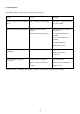
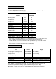
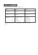
Specifications


2 Preparing for use
2.1 Electrical connection
Before connecting the machine to the power
supply, check that your supply voltage
corresponds with that marked on the rating
label on the handle of the machine.
The power supply cord plus any extension
leads should not exceed 30m in total,
otherwise you may experience problems
starting up the machine. The cross-section
of any extension cable wiring must be at
least 2,5 mm².
UK only
The supply cord is fitted with a non
rewireable plug containing a 13 amp fuse.
Should the fuse require replacement it must
only be replaced by a 13 amp fuse
conforming to BS1362, and the fuse cover
must be refitted. If the fuse cover is lost the
plug must not be used until the correct
replacement cover is fitted.
IMPORTANT - If the supply cord is
damaged, it must only be replaced by a
special cord available from the
manufacturer or an authorised service
agent.
WARNING -THIS APPLIANCE MUST BE
EARTHED
3 Controls
The operating controls for all models are
located on the handle (Fig. 1).
1 - Switch trigger, left hand
Used to switch motor ON and OFF. Can
only be operated with handle in working
position, and if left hand interlock button
(2) has previously been depressed
2 - Interlock button, left hand
This must be depressed initially to
enable left hand switch trigger to switch
motor on.
3 - Switch trigger, right hand
Used to switch motor ON and OFF. Can
only be operated with handle in working
position, and if right hand interlock button
(4) has previously been depressed.
4 - Interlock button, right hand
This must be depressed initially to
enable right hand switch trigger to switch
motor on.
5 - Handle adjustment lever
Used to adjust handle to comfortable
working height. Note: For safety reasons
the machine cannot be operated unless
the handle is moved to a working height.
6 - Solution feed lever
Operates flow valve in solution tank (if
fitted).
- Pull lever to release solution.
- Release lever to stop flow.
Cable winder
Used to hold supply cord in place on
handle when machine is not in use.
Neon indicator (on handle)
Lights when the machine is connected to
the power supply.
3.1 Fitting a brush or drive disc
WARNING - This appliance has been
designed for use with the brushes, pad
driver and pads specified by the
manufacturer. The fitting of other
accessories may affect its performance
and safety.
Always ensure machine is unplugged before
fitting or removing parts.
• Adjust handle to the fully upright position.
• Pull handle down until it rests on the floor
and the brush guard is raised.
• Fit the brush/drive disc onto the drive
plate and rotate it anti-clockwise until
secure.
• Return machine to its normal upright
position in readiness for starting.
• IMPORTANT - Never allow the cleaning
head to rest on a brush or pad when
not in use.
3.2 Adjusting the handle height
Select the most comfortable handle height
using the adjustment lever as previously
described (see Controls) and lock in
position.
4 Operation
The normal movement of a machine in use
is from side to side across the floor. This is
achieved automatically by raising or
lowering the handle whilst it is engaged in
the normal working position.
Lowering the handle thereby increasing the
pressure at the rear of the brush/drive disc,
moves the machine to the left. Raising the
handle increasing the pressure on the front
of the brush/drive disc moves the machine
to the right.
Inexperienced users are advised to practise
controlling the machine on a smooth floor
until they can handle the machine
confidently.
Practice and some strength are required to
operate the machine on uneven floors
The rear transport wheels should be raised
off the floor whilst cleaning (Fig 3)
Effective cleaning and polishing is achieved
by moving the machine in a backwards
direction.
Do not leave the machine standing on a
brush or pad when not in use.