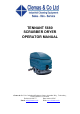
TENNANT 5680 SCRUBBER DRYER OPERATOR MANUAL Clemas & Co. Unit 5 Ashchurch Business Centre, Alexandra Way, Tewkesbury, Gloucestershire, GL20 8NB. Tel: 01684 850777 Fax: 01684 850707 Web: www.clemas.co.uk Email: info@clemas.co.
CONTENTS CONTENTS Page SAFETY PRECAUTIONS . . . . . . . . . . . . . . . . . 3 OPERATION . . . . . . . . . . . . . . . . . . . . . . . . . . . . OPERATOR RESPONSIBILITY . . . . . . . . MACHINE COMPONENTS . . . . . . . . . . . . CONTROL PANEL SYMBOLS . . . . . . . . . CONTROLS AND INSTRUMENTS . . . . . . STEERING HANDLES . . . . . . . . . . . . . ON-OFF KEY SWITCH . . . . . . . . . . . . SCRUB SWITCH . . . . . . . . . . . . . . . . . SCRUB HEAD STRAP (DISC HEAD) SQUEEGEE LEVER . . . . . . . . . . . . . . .
CONTENTS Page SPECIFICATIONS . . . . . . . . . . . . . . . . . . . . . . . 73 GENERAL MACHINE DIMENSIONS/CAPACITIES . . . . . . . . . . . 73 FaST SYSTEM (OPTION) . . . . . . . . . . . . . 74 ec--H2O SYSTEM (OPTION) . . . . . . . . . . . 74 GENERAL MACHINE PERFORMANCE . 74 POWER TYPE . . . . . . . . . . . . . . . . . . . . . . . 75 TIRES . . . . . . . . . . . . . . . . . . . . . . . . . . . . . . . 75 MACHINE DIMENSIONS . . . . . . . . . . . . . . 76 2 5680 330459 (10--08) Home Find... Go To..
SAFETY PRECAUTIONS SAFETY PRECAUTIONS The following symbols are used throughout this manual as indicated in their description: WARNING: To warn of hazards or unsafe practices that could result in severe personal injury or death. FOR SAFETY: To identify actions that must be followed for safe operation of equipment. This machine is designed solely for scrubbing dirt and dust in an indoor environment. Tennant does not recommend using this machine in any other environment.
SAFETY PRECAUTIONS The safety labels appear on the machine in the locations indicated. If these or any label becomes damaged or illegible, install a new label in its place. FLAMMABLE MATERIALS LABEL -LOCATED ON THE UNDERSIDE OF THE SOLUTION TANK COVER. FOR SAFETY LABEL -- LOCATED ON THE OPERATOR CONSOLE. 353417 BATTERY CHARGING LABEL -- LOCATED ON THE UNDERSIDE OF THE SOLUTION TANK. 4 FLAMMABLE SPILLS LABEL -- LOCATED ON THE OPERATOR CONSOLE. 5680 330459 (10--00) Home Find... Go To..
OPERATION OPERATION OPERATOR RESPONSIBILITY - The operator’s responsibility is to take care of the daily maintenance and checkups of the machine to keep it in good working condition. The operator must inform the service mechanic or supervisor when the maintenance intervals are required as stated in the MAINTENANCE section of this manual. - Read this manual carefully before operating this machine. FOR SAFETY: Do not operate machine, unless operation manual is read and understood.
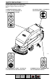
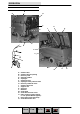
OPERATION MACHINE COMPONENTS B A D F C H J K A I G E L C M Q M N O P A. B. C. D. E. F. G. H. I. J. K. L. M. N. O. Solution tank Solution tank fill opening Recovery tank Steering handles Squeegee Squeegee lever Squeegee down pressure cams Recovery tank drain hose Solution tank hose Support arm Stop arm Batteries Scrub head Scrub brush access cover FaST solution system (option) ec- H2O System Module (option) P. Heavy duty scrub head strap Q.
OPERATION CONTROL PANEL SYMBOLS These symbols identify controls and displays on the machine: Key switch Circuit breaker #1--scrub head actuator Variable flow or rate Circuit breaker #2--vacuum fan motor Solution flow Circuit breaker #3--machine propel Scrub brushes down and on Circuit breaker #4--left brush motor Scrub brushes up and off Circuit breaker #5--right brush motor Heavy scrub brush down pressure Circuit breaker #6--FaST Circuit breaker #6--ec--H2O 7 5680 330459 (10--08) Home Find
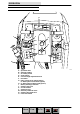
OPERATION CONTROLS AND INSTRUMENTS A B B J F O C H G E I D CB4 CB5 K CB6 CB1 K CB2 CB3 L N M A. B. C. D. E. F. G. H. I. J. K. L. M. N. O.
OPERATION STEERING HANDLES The steering handles control the machine speed and direction. Forward: Rotate the steering handles forward. The further forward you rotate the steering handles, the faster the machine will go. Backward: Rotate the steering handles backwards toward you. Turning: Push the machine in the direction of the turn with the steering handles. The machine will turn on the swivel casters. 9 5680 330459 (10--00) Home Find... Go To..
OPERATION Stop: Release the steering handles. The steering console height is adjustable. Adjust: Turn the console adjustment knob counterclockwise to loosen the knob. Move the console up or down to the desired height. Then turn the knob clockwise to tighten the knob, and lock the console in position. ON-OFF KEY SWITCH The on-off key switch controls machine power with a key. On: Turn the key to the right. Off: Turn the key to the left. 10 5680 330459 (10--00) Home Find... Go To..
OPERATION SCRUB SWITCH The scrub switch controls the scrubbing operations. Lower brushes and start scrubbing: Press the top of the switch. Raise brushes and stop scrubbing: Press the bottom of the switch. NOTE: The scrub brushes do not start until the steering handles are rotated forward or backward. NOTE: The scrub switch also controls the FaST/ec-H2O system (option) when the FaST/ec-H2O system is enabled with the FaST/ec-H2O switch.
OPERATION HOURMETER The hourmeter records the number of hours the machine has been powered on. This information is useful when servicing the machine. BATTERY DISCHARGE INDICATOR The battery discharge indicator shows the charge level of the batteries. When the batteries are fully charged, the indicator on the far right is lit. As the batteries discharge, the indicator will move along the display to the left. Recharge the batteries when the indicator flashes.
OPERATION ec- H2O SWITCH (OPTION) The ec--H2O switch (option) enables the ec--H2O (electrically converted water) system. When the ec--H2O system is enabled, it is turned on and off with the scrub switch. Enable the ec--H2O system: Press the top of the ec--H2O switch. Enable conventional scrubbing: Press the bottom of the ec--H2O switch. NOTE: Disable the ec--H2O system before using the machine for conventional scrubbing. NOTE: The ec--H2O system will not start until the machine starts scrubbing.
OPERATION SOLUTION FLOW LEVER The solution flow lever controls the amount of solution flow to the floor. Increase: Push the lever forward. Decrease: Pull the lever backward. NOTE: A solenoid valve dispenses the solution to the scrub head. The valve opens when the steering handles are rotated forward, and closes when the steering handles are released in neutral position. NOTE: When using the FaST or ec--H2O system (option), the solution flow lever is nonfunctional.
OPERATION SOLUTION TANK HOSE The solution tank hose is used to drain the solution tank. The drain hose plug is removed by turning the plug latch to loosen the plug and pulling the plug out of the drain hose. The drain hose is plugged by placing the hose plug in the end of the hose and turning the plug latch to tighten the plug. RECOVERY TANK DRAIN HOSE The recovery tank drain hose is used to drain the recovery tank.
OPERATION STOP ARM The stop arm prevents the solution tank from fully closing when the tank is lowered. Push the arm in to lower the solution tank completely. SQUEEGEE DOWN PRESSURE CAMS The squeegee down pressure cams adjust the squeegee deflection along the entire length of the squeegee. Increase: Turn the cams clockwise. Decrease: Turn the cams counter-clockwise. PARKING BRAKE The parking brake is controlled with a foot pedal and a release lever located by the squeegee.
OPERATION HOW THE MACHINE WORKS The scrub components of the machine are a solution tank, scrub brushes or pads, a squeegee, a vacuum fan, and a recovery tank. Water and detergent, from the solution tank, flow to the floor through a solution valve to the scrub brushes or pads. The brushes or pads scrub the floor. As the machine is moved forward the squeegee wipes the dirty solution off the floor, which is then picked up and drawn into the recovery tank.
OPERATION FaST SCRUBBING SYSTEM (OPTION) The FaST (Foam Scrubbing Technology) system operates by injecting the FaST PAK concentrate agent (A) into the system with a small amount of water and compressed air. This mixture creates a large volume of expanded wet foam. A The expanded foam mixture is then dispersed onto the floor (B) while the machine is scrubbing. When the squeegee picks up the mixture, the patented foaming agent has collapsed and is recovered into the recovery tank.
OPERATION ec- H2O SYSTEM (OPTION) The ec--H2O (electrically converted water) system operates by producing electrically activated water for cleaning. Normal water passes through a module where it is oxygenated and charged with an electric current. The electrically converted water changes into a blended acidic and alkaline solution forming a neutral pH cleaner.
OPERATION PRE-OPERATION CHECKLIST Check over this list of items before operating the machine: - Check under the machine for leaks. - Check for wire, string, or twine wrapped around the scrub brushes. - Check the squeegees for wear or damage. - Check the squeegee suction hose for obstructions. - Check the recovery tank cover seals for wear or damage. - Check that the vacuum fan inlet filter is clean. - FaST Scrubbing: Check the FaST PAK (option) concentrate agent level, replace carton as needed.
OPERATION INSTALLING FaST PAK AGENT (OPTION) NOTE: Machine must be equipped with the FaST option before the FaST PAK agent can be installed. 1. Remove the perforated knock--outs from the FaST PAK Floor Cleaning Concentrate carton. Do not remove the bag from the carton. Pull out the bag’s hose connector on the bottom of the bag and remove the hose cap from the connector. NOTE: The FaST PAK Floor Cleaning Concentrate is specifically designed for use with the FaST system scrubbing application.
OPERATION 4. Place the FaST PAK carton in the carton holder under the front cover of the machine. Connect the supply hose to the FaST PAK bag. NOTE: If any dried concentrate is visible on the supply hose connector or the on the FaST PAK connector, soak and clean with warm water. 5. Make sure to connect the supply hose onto the hose storing plug when the supply hose is not connected to the FaST PAK. This will prevent the FaST solution system from drying out and clogging up the hose. 6.
OPERATION STARTING THE MACHINE 1. Turn the machine power on. FILLING THE TANKS 1. Start the machine. 2. Drive the machine to the filling site. 3. Turn the machine power off. FOR SAFETY: Before leaving or servicing machine, stop on level surface, turn off machine, and remove key. 23 5680 330459 (3--08) Home Find... Go To..
OPERATION 4. CONVENTIONAL SCRUBBING: Open the solution tank cover and partially fill the solution tank with water. Pour the required amount of detergent into the solution tank fill opening. Continue filling the solution tank with water 25 mm (1 in) below the bottom of the solution fill opening channel. FOR SAFETY: When using machine, follow mixing and handling instructions on chemical containers. 5.
OPERATION SCRUBBING AND BRUSH INFORMATION D Pick up oversized debris before scrubbing. Pick up pieces of wire, string, twine, etc., which could become wrapped around the scrub brush. D Plan the scrubbing in advance. Try to arrange long runs with minimum stopping and starting. Do an entire floor or section at one time. D Try to scrub as straight a path as possible. Avoid bumping into posts or scraping the sides of the machine.
OPERATION Cylindrical polypropylene scrub brush -- This cylindrical brush uses a softer, general purpose polypropylene bristle to lift lightly compacted soilage without scuffing high-gloss coated floors. Cylindrical nylon scrub brush -- This cylindrical brush is recommended for scrubbing coated floors. Cleans without scuffing. Cylindrical super abrasive bristle scrub brush -- Nylon fiber impregnated with abrasive grit to remove stains and soilage.
OPERATION 4. FaST SCRUBBING: Press the top of the FaST switch to start the FaST system. NOTE: Leave the FaST switch in the CONVENTIONAL SCRUBBING position if not using the FaST system. ec--H2O SCRUBBING: Press the top of the ec--H2O switch to start the ec--H2O system. NOTE: Leave the ec--H2O switch in the CONVENTIONAL SCRUBBING position if not using the ec--H2O system. NOTE: The ec--H2O system indicator light will not turn on until the machine starts scrubbing.
OPERATION 5. Press the top of the scrub switch to lower the scrub head and begin scrubbing. 6. Lower the squeegee to the floor with the squeegee lever. 7. Adjust the solution flow to the floor as needed. NOTE: When using the FaST or ec--H2O system (option), the solution flow lever is nonfunctional. The FaST and ec--H2O system flow rates are pre--set. The ec--H2O module has optional flow rate settings. If solution flow adjustments are required, contact an Authorized Service Center. 8.
OPERATION DOUBLE SCRUBBING Double scrubbing is a method for removing heavy floor accumulations. This is done by making two passes over the area to be cleaned with the machine. Double scrubbing can be performed using the FaST SCRUBBING SYSTEM (option), ec--H2O SCRUBBING SYSTEM (option) or CONVENTIONAL SCRUBBING methods. 1. First, make a pass over the area scrubbing with the squeegee up. This dispenses the solution/foam over the area allowing the solution/foam to soak on the floor.
OPERATION STOP SCRUBBING 1. Release the steering handles. 2. Press the bottom of the scrub switch to stop scrubbing and raise the scrub brushes. 3. Propel the machine forward to pick up any solution left on the floor. 4. Raise the squeegee with the squeegee lever. 30 5680 330459 (9--02) Home Find... Go To..
OPERATION DRAINING AND CLEANING THE TANKS When you are finished scrubbing, or when the vacuum fan shuts off, signalling a full recovery tank, the recovery tank should be drained and cleaned. The solution tank then can be filled again for additional scrubbing. 1. Stop scrubbing. 2. Drive the machine next to a floor drain or sink. 3. Turn the machine power off. FOR SAFETY: Before leaving or servicing machine, stop on level surface, set parking brake, turn off machine, and remove key. 4.
OPERATION 5. Remove the recovery tank drain hose from the mounting clip. 6. Remove the recovery tank drain hose plug while holding the hose up, then slowly lower the drain hose to the floor drain or sink. 7. Check the solution tank, and empty any remaining solution with the solution tank drain hose. 8. Lift the solution tank to reach the recovery tank. 32 5680 330459 (9--02) Home Find... Go To..
OPERATION 9. Flush out the inside of the recovery tank with clean water. NOTE: DO NOT use steam to clean the tank. Excessive heat can damage the tanks and components. 10. Rinse off the float sensor on the side of the recovery tank. 11. Remove and clean the vacuum fan filter located in the recovery tank. Clean by shaking dust or rinsing pleats with low pressure water. Insert the filter back in to the recovery tank when finished.
OPERATION 12. An optional debris screen is available for the recovery tank entry. If your machine is equipped with this screen, remove and clean it daily. 13. When the recovery, and solution tanks have completely drained, replace the drain hose plugs. Place the drain hoses back onto the mounting clips on the machine. 14. Pull up on the support arm and lower the solution tank. Push the stop arm in to completely lower the solution tank. 15. Cylindrical scrub head: Remove and clean the debris trough.
OPERATION OPERATION ON INCLINES Drive the machine slowly on inclines. FOR SAFETY: When using machine, go slow on inclines and slippery surfaces. The maximum rated climb and descent incline with empty tanks is 8_, with full tanks is 6_. STOP THE MACHINE 1. Stop scrubbing. 2. Turn the machine power off. FOR SAFETY: Before leaving or servicing machine, stop on level surface, set parking brake, turn off machine, and remove key. 3. Set the machine parking brake. 35 5680 330459 (6--05) Home Find... Go To..
OPERATION POST-OPERATION CHECKLIST Check over this list of items after you have finished scrubbing with the machine powered on: - Check the battery charge level. NOTE: The reading on the battery discharge indicator may not be accurate when the machine is first powered on. Operate the machine a few minutes before reading the charge level of the batteries. Check over this list of items with the machine powered off: - Check for wire, string, or twine wrapped around the scrub brushes.
OPERATION MACHINE TROUBLESHOOTING Filter Problem Cause Remedy Trailing water -- poor or no water pickup Worn squeegee blades Rotate or replace squeegee blades Squeegee out of adjustment Adjust squeegee Vacuum hose clogged Flush vacuum hoses Vacuum fan screen dirty Clean inlet screen Debris caught on squeegee Remove debris Vacuum hose to squeegee or recovery tank disconnected or damaged Reconnect or replace vacuum hose Solution tank not completely closed Check for obstructions Heavy duty bat
OPERATION Problem Cause Remedy Poor propelling traction Tires slip on oily or waxed floors Contact Service Center Uneven brush down pressure Level scrub head FaST switch is set for Conventional scrubbing Set the FaST switch for FaST system scrubbing FaST Determine cause and reset the 10A circuit breaker button FaST System (option) does not operate circuit breaker tripped Clogged FaST PAK supply hose and/or connectors Soak connector and hose in warm water and clean FaST PAK carton is empty or
MAINTENANCE MAINTENANCE 3 9 10 1 7 11 8 6 6 2 4 8 5 353417 MAINTENANCE CHART Interval Daily Key 2 Squeegee 8 1 Scrub brushes or pads Recovery tank 3 3 Solution tank Vacuum fan filter Machine Disk scrub head skirt Cylindrical scrub head skirts 6 6 10 50 Hours 10 8 100 Hours Description 4 11 FaST PAK supply hose and connector (option) FaST Filter screen (option) Cylindrical brushes Rear casters Cylindrical scrub brush drive belts Procedure Check for damage and wear Check deflection an
MAINTENANCE Interval Key Description 500 Hours 9 Vacuum fan motor 10 FaST water and air filters 1000 (option) Hours 7 Scrub brush motors 5 Propelling motor 5 Transaxle Procedure Check motor brushes Replace Check motor brushes Check motor brushes Check lubricant level No. of Lubricant/ Service Fluid Points -1 -1 --GL 2 1 1 SPL -- Special lubricant, Lubriplate EMB grease (TENNANT part no. 01433--1) GL -- SAE 90 weight gear lubricant 40 5680 330459 (3--08) Home Find... Go To..
MAINTENANCE LUBRICATION REAR CASTERS The rear casters each have one grease fitting on the caster swivel. Lubricate the caster with a grease gun containing Lubriplate EMB grease (TENNANT part no. 01433--1) every 100 hours of machine operation. TRANSAXLE Check the transaxle lubricant level every 1000 hours of operation by removing one of the orange filler plugs. If needed, add SAE 90 weight gear lubricant. BATTERIES The batteries are unique in that they hold their power for long periods of time.
MAINTENANCE Keep all metallic objects off the top of the batteries, which may cause a short circuit. Replace any worn or damaged wires. Never add acid to the batteries, only distilled water. Always keep the battery caps on, except when adding water or taking hydrometer readings. Check the electrolyte level in each battery cell before and after charging, and after every 50 hours of operation. Do not charge the batteries unless the fluid is slightly above the battery plates.
MAINTENANCE CHARGING THE BATTERIES 1. Drive the machine to a flat, dry surface in a well-ventilated area. 2. Turn the machine power off and set the parking brake if your machine has this option. FOR SAFETY: Before leaving or servicing machine, stop on level surface, set parking brake, and turn off machine. 3. Lift up the solution tank to get access to the batteries. NOTE: The solution tank must be empty. 4. Check the water level in all battery cells.
MAINTENANCE NOTE: If the red “ABNORMAL CYCLE” lamp lights when the TENNANT charger is plugged into a wall outlet, the charger cannot charge the battery and there is something wrong with the battery. 7. The TENNANT charger will start automatically. When the batteries are fully charged, the TENNANT charger will automatically turn off. 8. After the charger has turned off, unplug the charger from the wall outlet. 9. Unplug the charger connector from the battery connector on the machine.
MAINTENANCE SCRUB HEAD The machine is equipped with a disk brush scrub head. The scrub head contains skirts to control over-spray from the scrub brushes. DISK BRUSH SCRUB HEAD SKIRT Make sure the scrub head skirt touches the floor all the way around when the scrub head is lowered. Check the skirt for damage or wear daily. NOTE: Replace the scrub head skirt when it is damaged or no longer is able to touch the floor. CYLINDRICAL BRUSH SCRUB HEAD SKIRTS The four head skirts should just touch the floor.
MAINTENANCE REMOVING OR REPLACING THE SCRUB HEAD The scrub heads are available in three widths. NOTE: When you change to a different width scrub head, be sure to install the appropriate width squeegee and machine front cover. 1. Lower the scrub head. 2. Turn the machine power off. FOR SAFETY: Before leaving or servicing machine, stop on level surface, set parking brake, and turn off machine. 3. Remove the machine front cover. 46 5680 330459 (6--05) Home Find... Go To..
MAINTENANCE 4. Disconnect the solution line from the scrub head tee fitting. 5. Disconnect the wire harness from each scrub motor. 6. Disconnect the scrub head from the guide by removing the clevis pin. 47 5680 330459 (9--02) Home Find... Go To..
MAINTENANCE 7. Disconnect the lift arms from the scrub head by removing the two clevis pins. 8. Mark the location of the actuator tube on the actuator shaft before disconnecting the actuator. Disconnect the actuator from the scrub head by removing the clevis pin. 9. To install the scrub head, connect the lift arms to the scrub head with the two clevis pins. 10. Connect the scrub head to the guide with the clevis pin. 11.
MAINTENANCE LEVELING THE SCRUB HEAD 1. Make sure the scrub head is lowered to the floor. 2. Check the level of the scrub head by measuring the distance from the top of the scrub head, to the floor at all four corners. The scrub head should measure the same on all four corners. 3. If the scrub head is not level at all four corners, loosen the jam nut on the adjustment screw located on the top of the scrub head. Turn the adjustment screw until the scrub head measures level. Tighten the jam nut. 4.
MAINTENANCE SCRUB BRUSHES AND PADS The scrub brushes should be checked daily for wire or string tangled around the brush or drive hub. The brushes should also be checked for any damage and wear. DISK BRUSHES The disk brushes should be replaced if large amounts of bristles are missing, or if the remaining bristles’ length is less than 10 mm. Cleaning pads must be placed on pad drives before they are ready to use. The cleaning pad is held in place by a pad holder.
MAINTENANCE 4. Turn the brush/pad driver until you can see the brush spring clip. 5. Press the spring clip together with your thumb and index finger. The brush/pad driver will drop off the drive hub. 6. Pull the brush/pad driver out from under the scrub head. 51 5680 330459 (9--02) Home Find... Go To..
MAINTENANCE 7. PAD DRIVER ONLY: Turn the pad driver over to access the spring clip underneath. 8. Press the spring clip together with your thumb and index finger to remove the center disk. 9. Flip or replace the scrub pad, center the scrub pad on the pad driver. 52 5680 330459 (9--02) Home Find... Go To..
MAINTENANCE 10.Replace the center disk to secure the pad in place on the driver. 11. Place the new scrub brush/pad driver on the floor in front of the scrub head. Push the brush under the scrub head. 12. Line up the drive socket with the drive plug. 13. Lift the scrub brush/pad driver assembly into the drive plug. 14. Check to make sure the brush/pad driver assembly is securely mounted on the brush drive hub. 15. Close the scrub head access cover. 16. Repeat for the other brush/pad driver.
MAINTENANCE CYLINDRICAL BRUSHES Check the brush taper and rotate the brushes from front-to-rear every 50 hours of operation, for maximum brush life and best scrubbing performance. The cylinder brushes should be replaced if large amounts of bristles are missing, or if the remaining bristles’ length is less than 10 mm (0.38 in). NOTE: Be sure to replace brushes in sets. Otherwise one brush will be more aggressive than the other. REPLACING THE CYLINDRICAL BRUSHES 1. Raise the scrub head. 2.
MAINTENANCE 6. Insert the Idler plug of the idler door into the brush. 7. Push down on the door to catch the door in the scrub head, then pull up on the door to latch it in the spring. 8. Repeat for the other brush on the other side of the scrub head. NOTE: The idler doors have stamped letters that correspond with letters on the scrub head. Make sure the idler doors are placed back on the same side of the scrub head that they were originally removed from.
MAINTENANCE 6. Observe the shape of the brush patterns. If the brush patterns have parallel sides, the brushes do not need taper adjustment. 10355 If one or both of the brush patterns are tapered, the brushes will have to be adjusted to straighten the brush pattern. 10356 A. Remove the idler door by pushing down on the mounting spring and the idler door, then pulling out on the bottom of the door. Push down on the spring until the door releases from the scrub head. Pull the idle plug off the brush. B.
MAINTENANCE C. Turn the idler shaft to raise or lower the end of the brush as needed to straighten the brush pattern. Tighten the mounting screw. D. Check the brush patterns again and readjust as necessary. The brush patterns should be the same width. If one is narrower then the other, loosen the jam nut on the adjustment screw located on the top of the scrub head. Turn the adjustment screw clockwise to increase the front brush pattern width.
MAINTENANCE Rinse and wipe off the sensors daily on machines with float sensors installed inside the recovery tank. A vacuum fan filter is located in the recovery tank. Remove and clean this filter daily. Clean by shaking dust or rinsing pleats with low pressure water. NOTE: Be sure the vacuum filter is dry before reinstalling it in the machine. An optional debris screen is available for the recovery tank entry. If your machine is equipped with this screen, remove and clean it daily.
MAINTENANCE FaST SYSTEM (OPTION) FaST SYSTEM MAINTENANCE Every 1000 hours replace the water filter and air filter located in the FaST detergent injector. Order filter kit p/n 9003009. To access the detergent injector assembly, lower the scrub head and remove the front cover. Remove the injector assembly from clamps. Replace the water and air filter. An 8mm hex wrench required to install new water filter. Water Filter (50 Mesh/Brown) Air Filter (50 Mesh/Brown) 59 5680 330459 (3--08) Home Find...
MAINTENANCE FaST SYSTEM FILTER SCREEN The FaST system filter screen is located under the solution tank and filters the water from the solution tank as it flows into the FaST system. Remove the filter screen bowl and clean the filter screen after every 50 hours of machine operation. Empty the solution tank before removing the filter. FaST SUPPLY HOSE CONNECTOR The FaST supply hose connector is located below the FaST PAK holder. Soak the connector in warm water if detergent buildup is visible.
MAINTENANCE ec- H2O SYSTEM (OPTION) ec- H2O MODULE FLUSH PROCEDURE This procedure is only required when an alarm sounds and the ec--H2O system indicator light begins to blink red. 1. Drain the solution tank and recovery tank of all water. 2. Pour 2 gallons (8 liters) of white or rice vinegar into the solution tank at full strength. Do not dilute. (p/n 1050552 -- Vinegar, 2.5 gals/10 ltrs) NOTE: Use white or rice vinegar only. The acidity level should be between 4--8%.
MAINTENANCE SQUEEGEE The squeegee assembly channels water into the vacuum fan suction. The front blade channels the water, and the rear blade wipes the floor. Check the squeegee blades for damage and wear daily. Rotate or replace either of the squeegee blades if the leading edge is torn or worn half-way through the thickness of the blade. The squeegee can be adjusted for leveling and deflection.
MAINTENANCE 4. Loosen the two mounting knobs. 5. Pull the squeegee off the machine. INSTALLING THE SQUEEGEE ASSEMBLY 1. Make sure the squeegee is raised. 2. Place the squeegee under the squeegee pivot. 3. Slide the squeegee frame onto the squeegee pivot. 4. Tighten the mounting knobs. 5. Push the squeegee suction hose on the squeegee. LEVELING THE SQUEEGEE Leveling of the squeegee assures even contact the length of the squeegee blade with the surface being scrubbed.
MAINTENANCE 5. If the deflection is not the same over the full length of the blade, turn the squeegee leveling bolt counter-clockwise to increase the deflection at the ends of the squeegee. Turn the squeegee leveling bolt clockwise to decrease the deflection at the ends of the squeegee blade. 6. Drive the machine forward again with the squeegee down to check the squeegee blade deflection. 7. Readjust the squeegee blade deflection if necessary.
MAINTENANCE SQUEEGEE BLADES The squeegee has two squeegee blades, the front and back. Each blade has four wiping edges. To use them all, start with one wiping edge. To use the next wiping edge, rotate the blade end-for-end. To use the next wiping edge, rotate the top edges down, bottom edges up. To use the last edge, rotate the blade end-for-end. Replace any worn or damaged squeegee blades. REPLACING OR ROTATING THE REAR SQUEEGEE BLADE 1. Make sure the squeegee is raised off the floor. 2.
MAINTENANCE 4. Pull off the rear retaining band. 5. Pull off the rear squeegee blade. 6. Insert the rotated or new squeegee blade and then insert the retainer band. 7. Tighten the two retention knobs until the ends of the front and rear squeegee blades touch. Do not overtighten. 66 5680 330459 (9--02) Home Find... Go To..
MAINTENANCE REPLACING OR ROTATING THE FRONT SQUEEGEE BLADE 1. Make sure the squeegee is raised off the floor. 2. Turn the machine power off. FOR SAFETY: Before leaving or servicing machine, stop on level surface, set parking brake, and turn off machine. 3. Remove the squeegee from the machine. See REMOVING THE SQUEEGEE ASSEMBLY. 4. Remove the rear squeegee blade and retainer. See REPLACING OR ROTATING THE REAR SQUEEGEE BLADE. 5. Loosen the two remaining knobs on top of the squeegee assembly. 6.
MAINTENANCE BELTS AND CHAINS BRUSH DRIVE BELT The two brush drive belts are located on the cylindrical brush scrub head. The belts drive the cylindrical brushes. Proper new belt tension is a 3 mm (0.1 in) deflection from a force of 1.37 to 1.48 kg (3.0 to 3.26 lb) at the belt midpoint. When reusing an old belt, measure and record the belt tension before removal, so that the belt can be reinstalled at the same tension. If the old belt tension was not recorded, the recommended force per old belts is 1.
MAINTENANCE PUSHING AND TRANSPORTING THE MACHINE PUSHING THE MACHINE If the machine becomes disabled, it can be pushed if necessary. Unplug the drive motor from the electrical harness before attempting to push a disabled machine. The machine will become easier to maneuver when it is unplugged. ATTENTION! Do not push the machine for a long distance and without unplugging the drive motor or damage may occur to the propelling system. Only push a disabled machine for a very short distance and do not exceed 3.
MAINTENANCE 4. Unplug the drive motor from the electrical harness before attempting to winch the machine. The machine will become easier to maneuver when it is unplugged. 5. Position the machine onto the truck or trailer as far as possible. If the machine starts to veer off the centerline of the truck or trailer, stop and straighten the machine. 6. Lower the scrub head with the brushes or pad drivers installed, lower the squeegee when transporting the machine.
MAINTENANCE MACHINE JACKING Check that both the solution and recovery tanks are empty before attempting to jack up the machine. You can jack up the machine for service anywhere under the recovery tank. Use a piece of wood to distribute the machine weight load. Always stop the machine on a flat level surface and block the machine tires before jacking up the machine. FOR SAFETY: When servicing machine, block machine tires before jacking machine up.
MAINTENANCE Continue with the freeze protection procedure if machine is equipped with the ec--H2O system. ec- H2O Model: 4. Press and release the flush switch on the ec--H2O module to cycle the antifreeze through ec--H2O system.When the antifreeze is visible, press the switch again to turn off the module. The module is located behind the front cover. IMPORTANT: Before operating machine, the antifreeze must be flushed from the module as described below.
SPECIFICATIONS SPECIFICATIONS GENERAL MACHINE DIMENSIONS/CAPACITIES Item Dimension/capacity Length with cylindrical scrub head 1.600 mm Length with 700 mm disk scrub head 1.625 mm Length with 800 mm disk scrub head 1.660 mm Length with 900 mm disk scrub head 1.690 mm Width (less squeegee and scrub head) 720 mm Height 1.
SPECIFICATIONS FaST SYSTEM (OPTION) Item Measure Solution pump 36 Volt DC, 5A, 5,7 LPM (1,5 GPM) open flow, 45 psi bypass setting Solution flow rate 0,83 LPM (0,22 GPM) Detergent pump 36 Volt DC Concentrate flow rate 0,9 CC/Minute (0,03 Ounces/Minute) Concentrate to water dilution ratio 1:1000 Air pump 24 Volt DC, 0,6 Maximum Amp draw Air pump flow rate 8,7 LPM (0,3 CFM) open flow ec- H2O SYSTEM (OPTION) Item Measure Solution pump 36 Volt DC, 5A, 5,7 LPM (1,5 GPM) open flow, 45 psi bypass
SPECIFICATIONS POWER TYPE Type Quantity Volts Ah Rating Weight Batteries 6 6 235 @ 20 hr rate 30 kg 6 6 335 @ 20 hr rate 47 kg Type Use VDC Kw Electric Motors Scrub brush (disk) 36 0,56 Scrub brush (cylindrical) 36 0,56 Vacuum fan 36 0,63 Propelling 36 0,37 Type VDC amp Hz Phase VAC Chargers (Smart) 36 20 60 1 115 36 30 60 1 115 TIRES Location Type Size Front (2) Foam filled, non--marking 4,10/3,5 -- 6 Rear, casters (2) Solid, non-marking 127 mm x 35 m
SPECIFICATIONS 950 mm 1.065 mm 1.155 mm 1.625 mm 1.660 mm 1.690 mm 1.090 mm 720 mm 353416 MACHINE DIMENSIONS 76 5680 330459 (9--02) Home Find... Go To..