Cleo Eco Pro Steam generator INSTALLATION- AND OPERATING INSTRUCTIONS 90549002 | EN
Contents 1 1.1 1.2 Introduction To the very beginning Notes on the installation and operating instructions 4 4 4 2 For your safety 6 3 3.1 3.2 3.3 3.4 3.5 3.6 3.7 3.7.1 3.7.2 3.8 3.9 Product Overview Models overview Identification of the unit Steam generator construction Functional description Generator system overview Options Accessories Accessories overview Accessory details Standard delivery Storing/Transportation/Packaging 8 8 9 10 11 13 15 16 16 17 20 20 4 4.1 4.1.1 4.1.2 4.2 4.
1 Introduction 1.1 To the very beginning We thank you for having purchased the steam generator Cleo Eco Pro. The steam generator Cleo Eco Pro. incorporates the latest technical advances and meets all recognized safety standards. Nevertheless, improper use of the Cleo Eco Pro may result in danger to the user or third parties and/or impairment of material assets.
Explanation of the symbols used in this manual CAUTION! The catchword “CAUTION” designates notes in this documentation that, if neglected, may cause damage and/or malfunction of the unit or other material assets. WARNING! The catchword “WARNING” used in conjunction with the general caution symbol designates safety and danger notes in this documentation that, if neglected, may cause to injury to persons.
2 For your safety General Every person working with the Cleo Eco Pro must have read and understood the present installation and operating instructions before carrying out any work. Knowing and understanding the contents of the installation and operating instructions is a basic requirement for protecting the personnel against any kind of danger, to prevent faulty operation, and to operate the unit safely and correctly.
Danger that may arise from the unit DANGER! Danger of electric hazard! The Cleo Eco Pro is mains powered. One may get in touch with live parts when the unit is open. Touching live parts may cause severe injury or danger to life. Prevention: Before carrying out any work set the Cleo Eco Pro out of operation as described in chapter 6.5 (switch off the unit, disconnect it from the mains and stop the water supply) and secure the unit against inadvertent powerup.
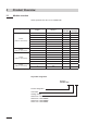
3 Product Overview 3.1 Models overview Steam generator Cleo Eco Pro is available with: Heating voltage ** Max. steam capacity in kg/h Model Cleo Eco Pro Unit small 5 534 1 8 834 1 15 1534 1 23 2364 1 32 3264 1 45 4564 1 65 6564 1 400V3 (400 V/3~/50...60 Hz) 400V2 (400 V/2~/50...60 Hz) 230V3 (230 V/3~/50...60 Hz) 230V1 (230 V/1~/50...
3.2 Identification of the unit The identification of the unit is found on the type plate: type designation Heating voltage Maximum steam capacity per unit Admissible water supply pressure Serial number (7 digits) Type: Cleo Eco Pro Heating voltage: 400V / 3~ / 50...60Hz Steam capacity: 45.0 kg/h Water pressure: 1...10 bar Month/Year Ser.Nr.: XXXXXXX 02.10 Power: 33.8 kW Ctrl. Voltage: 230V / 1~ / 50...
3.
3.4 Functional description The steam generator Cleo Eco Pro is a pressureless steam generator that utilizes an electrode heating. The steam generator Cleo Eco Pro is designed for steaming via a steam distributor (steam distribution pipe, fan unit or steam distribution system MultiPipe).
Upon reaching the requested steam capacity, the inlet valve closes. If the steam generation decreases below a certain percentage of the required capacity, due to lowering of the water level (e.g. because of the evaporation process or drainage), the inlet valve opens until the required capacity is available again. If the required steam capacity is lower than the actual output, the inlet valve is closed until the desired capacity is achieved by lowering of the water level (evaporation process).
3.5 Steam generation system overview System overview steam generator 16 17 15 MultiPipe DV41 DV71 DS22 14 DS35 KS10 12 13 11 1 10 F OF 2 F OF 3 ON ON 4 5 Z261 9 6 7 8 125...1250 µS/cm 1...10 bar 1...
System overview room steam generation FAN4 N S W 14 FAN4 N M W FAN4 N L W 15 DS80 12 KS10 13 16 1 F OF 2 F OF 3 ON ON 10 4 11 5 Z261 9 6 7 8 125...1250 µs/cm 1...10 bar 1...
3.6 Options Cleo Eco Pro 522 524 532 534 822 824 832 834 1532 1534 2362 2364 Remote operating and fault indication PCB with relay contacts for the connection of remote displays for “Operation”, “Steam”, “Fault” and “Service”. 1xRFI Overpressure set Kit for mounting the water cup to the unit cover when operating the steam generation in systems with a duct air pressure of up to 10 kPa.
3.7 Accessories 3.7.1 Accessories overview Accessories for water installation Cleo Eco Pro... 522 524 532 534 822 824 832 834 Filter valve 1532 1534 2362 2364 3262 3264 4564 6564 4564 6564 Z261 (1 pcs. per system) Accessories for steam installation Cleo Eco Pro... 522 524 532 534 Steam distribution pipe (details see chapter 3.7.2) 2362 2364 3262 3264 1xDV71-... 2xDV71-... --- System 1 System 2 FAN4 N S W Steam hose / meter EcoTherm insulation hose / meter 1532 1534 1xDV41-...
3.7.2 Accessory details 3.7.2.1 Steam distribution pipe DV41-.../DV71-... The steam distribution pipes are selected on the basis of the duct width (for horizontal installation) or the duct height (for vertical installation) and the capacity of the steam generator. Important! Always select the longest possible steam distribution pipe (optimum generation distance). L B Steam distribution pipes for Cleo Eco Pro 1) Type DV41-.. Type DV71-..
3.7.2.2 MultiPipe steam distribution system H B the MultiPipe steam distribution system is used in ventilation ducts with a short generator distance (for the calculation of the steam generation distance refer to chapter 5.4.2). When ordering an MultiPipe system the duct dimension must be specified. Please consult the data in the following table. MultiPipe 1) 18 Number of steam connectors Max.
3.8.2.3 Fan units FAN4 N... The fan units FAN4 N... – in combination with the steam generator Cleo Eco Pro – is used for direct room steam generation. they are mounted above the unit to the wall. the type of fan unit is dependent on the steam capacity and on the type of the generator and can be gathered from the table in chapter 3.7.1. note: Further information on the fan units Fan4 n... can be found in the separate manual supplied with the fan unit.
3.8 Standard delivery The standard delivery includes: 3.9 – Steam generator Cleo Eco Pro with water drain hose and water connection hose G 3/4" G 3/8" equipped with the options ordered according to chapter 3.
4 Notes for the planning engineer 4.1 Selecting the unit version To select the unit version the following planning steps are required: 1. Calculating the required maximum steam capacity according chapter 4.1.1 2. Selecting the unit version from the table in chapter 4.1.2 4.1.
4.1.2 Selecting the unit Cleo Eco Pro 4564 400V3 Heating voltage ** Max. steam capacity in kg/h Model Cleo Eco Pro .. Unit small 5 534 1 8 834 1 15 1534 1 400V3 (400 V/3~/50...60 Hz) 400V2 (400 V/2~/50...60 Hz) 230V3 (230 V/3~/50...60 Hz) 230V1 (230 V/1~/50...60 Hz) Unit size Unit large 23 2364 1 32 3264 1 45 4564 1 65 6564 1 5 524 1 8 824 1 5 532 1 8 832 1 15 1532 1 23 2362 1 32 3262 1 5 522 1 8 822 1 ** Other heating voltages on request 4.
4.3 Selecting the control system The various control systems – System 1: Room steam control system 1 is suited for direct room steaming and air conditioning systems with mainly recirculated air. the steam sensor respectively is preferably located in the room itself or in the exhaust air duct. a1 B1 B2 B3 B4 pIe Y temperature sensor ventilation interlock airflow monitor safety sensor sensor External continuous controller (e.g.
– System 3: Supply air humidity control with continuous output limitation Supply air humidity control (humidity sensor installed in supply air duct) should be used only where room steam control is impracticable for technical reasons. Such systems always require a PIcontroller. The temperature sensor (A1) is located in the supply air duct after the steam distribution pipe. The temperature sensor (A2) for the continuous output limitation is located in the supply air duct before the steam distribution pipe.
5 Mounting and installation work 5.1 Important notes for mounting and installation work Qualification of personnel All mounting and installation work must be carried out only by well qualified personnel authorised by the owner. It is the owner’s responsibility to verify proper qualification of the personnel.
5.2 Installation overviews Installation overview duct generator External safety chain L1 N SC1SC2 X3 A1 / A2 Cleo Eco Pro ext. B3 B3 max. Continuous control 0-10V On/Off-Control JP1 JP1 On/Off Mode DV41 On/Off Mode CONT.SIGN V+ IN GND DV71 X1 Pmax 1500 Pa Pmin -800 Pa DS22 A1 + – min. 20 % + Cleo Eco Pro ext. On/Off Heating voltage in. min. 20 % – in. Øm mm 200 min. 300 mm KS10 Steam installation see chapter 5.4 A2 0-10V 30 0m m DS35 X1 Cleo Eco Pro ext. Rm min.
Installation overview room generator External safety chain L1 N SC1SC2 X3 Cleo Eco Pro ext. B3 max. Continuous control 0-10V On/Off-Control JP1 JP1 On/Off Mode CONT.SIGN V+ IN GND FAN4 N S W Steam installation see chapter 5.4 On/Off Mode CONT.SIGN V+ IN GND X1 FAN4 N M W FAN4 N L W X1 Cleo Eco Pro ext. B3 A1 / A2 A1 + – Cleo Eco Pro ext. A2 0-10V On/Off Heating voltage KS10 Ømin. 100 mm K1 L1 L2 L3 X0 L1 L2 L3 DS80 PE Q2 Mounting the unit see chapter 5.
Mounting the unit 5.3.1 Notes on locating the unit min. 400 mm 5.3 m 0m 40 in. m m 0m 25 in. m X Y 1 ... 40 °C max. 75 %rh IP20 Z 60...70 °C 00 .6 in m min. 600 mm m m Cleo Eco Pro ...
The installation site of the steam generator depends largely on the location of the steam distributor (see chapter 5.4). To ensure proper functioning of the steam humidifier and to obtain an optimal efficiency, the following points must be considered and observed when choosing the location for the steam generator: – Install the steam generator so that the length of the steam hose is kept as short as possible (max.
5.3.2 Mounting the generator Dimension a b c d e a b A Housing size small large 189 mm 246 mm 61 mm 52 mm 490 mm 547 mm 120 mm 180 mm 120 mm 180 mm c B B e d Procedure 1. Mark the attachment point “A” on the wall. 2. Drill hole for attachment point “A” (diameter: 8 mm, depth: 40 mm). 3. Insert the supplied plastic plug, and tighten the screw until the distance between the wall and the screw head is 4 mm. 4. Unlock the two screws fixing the front panel to the unit, then remove the front panel. 5.
5.3.3 Inspecting the installed unit Check the following points: Is the unit installed in the correct place (see chapter 5.3.1)? Is the supporting surface stable enough? Is the unit correctly aligned, vertically and horizontally? Is the unit properly secured (see chapter 5.3.
5.4 Steam installation 5.4.1 Overview steam installation DV41 DV71 Pmax 1500 Pa Pmin -800 Pa DS22 in. min. 20 % – min. 20 % + 30 0m m DS35 Rm min. 300 mm min. 5 % – FAN4 N S W in. Øm mm 200 FAN4 N M W FAN4 N L W min. 20 % Ømin. – 100 mm KS10 32 min. 20 % + DS80 min.
5.4.2 Positioning and mounting of the steam distribution pipes The location for the steam distribution pipes should be determined at the time of dimensioning the air conditioning system. Please note the following instructions to ensure proper steaming. Calculating the generator distance The water vapour, emitting from the steam distribution pipes, requires a certain distance to be absorbed by the ambient air so that it is no longer visible as steam.
Example given: ϕ1= 30 %rh, ϕ2= 70 %rh humidification distance Bn: 1,4 m (0.36 m for steam distribution system MultiPipe) Note: If the steam distance has to be reduced for technical reasons, the amount of steam per basic unit must be divided between two steam distribution pipes or the steam distribution system MultiPipe must be used. If this is the case, contact Cleopatra B.V.
before diffuser 1x before control sensor BN 5x before/after filter/register before/after fan, zone exit + 1.5 x BN BN 50 mm * 50 mm 1x * 2,5 x Bn before aerosol filter 1x BN BN Installation notes and dimensions The steam distribution pipes are designed for either horizontal installation (on the duct wall) or, with accessories, for vertical installation (in the duct floor). The outlet orifices should always point upwards and at right angles to the airflow.
Positioning the steam distribution pipes in the duct In positioning the steam distribution pipes, the following dimensions should be observed: H 1/2 H 2/3 H hmin 1/3 1/2 H min.= 250 mm 1/2 H ≥400 mm H min.= 200 mm 1/3 gmin 3/7 H 1/2 H 1/3 1/3 3/7 H 2/7 2/7 2/7 2/7 H min.= 400 mm H min.= 350 mm H min.= 300 mm g min.= 100 mm h min.= 85 mm Note: When locating the MultiPipe steam distribution system please note the instructions in the separate documentation for this product.
5.4.3 Installing the steam distributors Detailed information on the installation of steam distribution pipes DV41 .., DV71... and MultiPipe steam distribution system can be found in the separate mounting instructions for these products.
5.4.4 Positioning and mounting of the fan units FAN4 N... the fan unit Fan4 n... is mounted on the wall separately above the unit. To allow the steam coming from the fan unit to spread out evenly, without condensing on obstacles (ceilings, joists, pillars, etc.), the following minimum dimensions must be observed when selecting the location for the fan unit. D D B E C A md max. a min. B min. C approx. D approx. e min. E max. (max. steam hose length) FAN4 N S W 8 kg/h 4.0 m 1.0 m 2.2 m 1.
Installing the steam hose Important! Use original steam and condesate hose from Cleopatra B.V. exclusively. Other types of hoses can cause undesired operational malfunctions. Instructions for the hose layout The hose layout depends on the position of the steam distribution pipe: – Steam distribution pipe is mounted more than 500 mm above the top edge of the generator: min. 20 % + min. 20 % + max. 4 m min. 300 mm Ømin. 200 mm in. min. 300 mm Rmin. 300 mm min. 20 % Rm Ømin. 200 mm max.
– Steam distribution pipe is mounted less than 500 mm above the top edge of the generator: min. 5 % – + Rm in. 30 0m m max. 4 m in. Øm mm 200 min. 300 mm min. 20 % – min. 300 mm min. 20 % Obstacle min. 20 % + in. Rm 300 max. 4 m mm min. 20 % min. 5 % Rmin . 30 min. 300 mm 0m m + min. 20 % – in. Øm mm 200 Install condensate drain (accessory) at the lowest point min. 300 mm min. 20 % – in.
– The steam hose should be kept as short as possible (max. 4 m) while observing the minimum bend radius of 300 mm. Important! Allowance must be made for a pressure loss of 10 mm water column (approx. 100 Pa) per meter steam hose. Note: If your particular installation exceeds the maximum steam hose length of 4 m contact Cleopatra B.V. In any case, steam hoses longer than 4 m must be insulated in their entire length (e.g. with insulation hose “EcoTherm”).
Steam line with fixed piping For steam lines with fixed piping, the same instructions apply to the laying of the piping as already described. min. 20 % + x. ma 4m Ømin. 200 mm in. 5x D min. 300 mm min. 300 mm min. 20 % – Rm The following additional notes should be observed: 42 – the minimum internal diameter of the steam line (diameter dependent on the steam generator) should be applied over the whole length of the piping. – Use exclusively copper pipe or stainless steel (min. DIN 1.
5.4.6 Common steam and condensate line errors 2. 3. 4. 5. 1. 1. Steam hose not led at least 300 mm perpendicularly upwards before first bend. 2. Minimum bend radius of steam hose of 300 mm not maintained (forming of condesate). 3. Siphon of the condensate hose not at least 300 mm below the steam distribution pipe. 4. No condensate drain installed at vertical transition. 5 . Steam hose not sloped (slope min. 20 %).
5.4.
5.5 Water installation 5.5.1 Overview water installation G 3/4" ø 30 mm G 3/4" G 3/4" ø 30 mm min. 50 cm ø14/7 mm ø14/7 mm G 1/2" G 3/8" ø 40/31 mm G 3/8" Z261 125...1250 µS/cm 1...10 bar 1...
5.5.2 Notes on water installation Water supply The water supply is to be carried out according to the figure found in chapter 5.5.1 and the applicable local regulations for water installations. The indicated connection specifications must be observed. – The installation of the filter valve (accessory “Z261”, alternatively a shutoff valve and a 5 µm water filter can be used) should be made as close as possible to the steam generator. – Admissible mains pressure 1.0 to 10.
5.5.
5.6 Electric installation 5.6.1 Wiring diagram Cleo Eco Pro Power board ES4 Card X4 1 CURRENT SENSOR LEV.SENSOR 2 S2 CPU board PE 1 ES4 ext. F1 (6.3 AT) JP1 F2 3 On/Off Mode Q2 X5 4 CPU BOARD J1 L1 L2 L3 X7 CONT.SIGN V+ IN GND X1 VD MAIN SUPPLY L1 N SC1SC2 X2 X3 F4 A1 + – 0-10V A3 L3 PE L1 L2 PE L1 PE Q2 J H1 L1 L2 400 V/3~/50..60 Hz 230 V/3~/50..60 Hz 2 1 2 3 4 5 6 ON S4 Manual Drain Low Conduct.
5.6.2 Notes on electric installation Important notes – The electric installation must be carried out according to the wiring diagram in chapter 5.6.1, the notes on electric installation as well as the applicable local regulations. All information given in the wiring diagram must be followed and observed. – All cables must be lead into the unit via the cable openings equipped with cable glands (e.g. option “CGcable gland”).
Control voltage supply CAUTION! – Before connecting, ensure that the mains voltage corresponds with the control voltage of the unit (230 V/1 50…60 Hz). – The generator must only be connected to a mains supply with a protective conductor. the connection to the control voltage is made in accordance with the wiring diagram, to the terminal “X3” on the power board.
Remote operating and fault indication H1 (Option “RFI”) The optional remote operating and fault indication PCB is to be connected to the control board via the terminal “J1”. The optional remote operating and fault indication PCB contains four potentialfree relay contacts for the connection of the following operating and fault indications: – “Error”: This relay is activated if an error is present. – “Service”: This relay is activated when the set service interval has expired.
5.6.
5.6.4 Inspecting the electrical installation Check the following points: Do the supply voltages for heating and control comply with the relevant voltages given in the wiring diagram? Is the correct ES4 Card inserted? Are the voltage supplies (heating and control voltage) correctly fused? Is the service switch “Q..
6 Operation 6.1 Function of the display and operating elements Drain/Info key – press key shortly: Opens and closes the drain valve (manual draining). Note: the drain valve is automatically closed after 10 minutes. – press key for a extended period of time (>3 sec.): activating the info mode red LED “Error” – in normal operating mode – The LED lights in case of a malfunction of the unit. Further operation is no longer possible, the heating voltage is interrupted.
6.2 Commissioning Proceed as follows when putting the unit into operation: 1. Examine the steam generator and installation for possible damage. DANGER! Damaged devices or devices with damaged installation may present danger to human life or cause severe damage to material assets. Damaged units and/or units with damaged or faulty installation must not be operated. 2. Check whether the front panel is mounted and fixed with the two screws. 3. Open the shutoff valve in the water supply line. 4.
6.3 Notes on operation 6.3.1 Function of the LED's in info mode The info mode is activated by pressing the drain/info key for an extended period of time (> 3 seconds). After activating the info mode: – first, the green LED flashes. The number of flashes indicates the current steam output in % of the maximum steam capacity. Green LED flashing ...
6.3.3 Inspections during operation During operation the Cleo Eco Pro and the generating system have to be inspected weekly. On this occasion check the following: • the water and steam installation for any leakage. • the steam generator and the other system components for correct fixing and any damage. • the electric installation for any damage. If the inspection reveals any irregularities (e.g.
7 Maintenance 7.1 Important notes on maintenance Qualification of personnel All maintenance work must be carried out only by well qualified and trained personnel authorised by the owner. It is the owner’s responsibility to verify proper qualification of the personnel. General note The instructions and details for maintenance work must be followed and upheld. Only the maintenance work described in this documentation may be carried out. Only use original Cleopatra B.V. spare parts to replace faulty parts.
7.2 Maintenance list To maintain operational safety the Cleo Eco Pro steam generator must be maintained at regular intervals. This is differentiated between the first maintenance after approx. 500 operating hours (I), steam cylinder replacement after the yellow LED lights (II) and annual maintenance (III). Below you will find a summary of the work to be carried out for each of the three maintenance stages. Components Interval I Replacement steam cylinder II Work to be done III X Remove and replace.
7.3 Removing and installing parts for maintenance 7.3.1 Removal and installation of the steam cylinder 1 2 1. Undo the two screws fixing the front panel to the unit using a screwdriver, then remove the front panel. 2. Release the hose clamp on the steam hose using a screwdriver, then detach the steam hose from the steam outlet connection of the steam cylinder. 3 4 3. Remove all plugs from the electrodes and from the level sensor. 4.
5 6 5. Carefully lift steam cylinder away from the cylinder receptacle, then remove it to the front. CAUTION! Put steam cylinder down carefully to avoid damage to the lower connection piece! 6. Carefully pull the drain screen out of the drain outlet of the steam cylinder. Note: this step must only be carried out if the drain screen is clogged (see chapter 8.2.2 “Unit faults”) and the steam cylinder can still be used.
Installation of the steam cylinder follows the reverse sequence. Observe the following: – Before installing the steam cylinder in the unit, check the Oring of the cylinder receptacle for damage and replace if necessary. – Moisten the Oring of the cylinder receptacle with water (do not use grease or oil), then insert steam cylinder into the receptacle and push it down to the stop.
7.3.2 Removal and installation of the drain cup 3 2 1 1. Release the hose clamp, then remove water drain hose from the connector on the water cup. 2. Undo the three screws fixing the drain cup to the unit using a screwdriver, then remove the drain cup downwards. 3. Remove Oring from the annular groove of the drain cup. Installation of the drain cup follows the reverse sequence. Before assembling check Oring of the drain cup for damage and replace if necessary.
7.3.3 Removal and installation of the water cup and the water hoses For removing the water cup and the water hoses the steam cylinder must be removed first (see chapter 7.3.1). 1. Release hose clamps using pliers, then disconnect all hoses from the corresponding connectors and remove the hoses. Note: The hoses connected to the water cup may also be removed together with the water cup (see illustration) and then disconnected from the connectors of the water cup outside the unit. 2.
7.3.4 Removal and installation of the drain valve 4 1 3 2 For removing the drain valve the steam cylinder must be removed first (see chapter 7.3.1). 1. Detach electric cables (polarity of the cables must not be observed). 2. Release hose clamp and remove the hose from the connector. 3. Loosen the two screws with Phillips screwdriver, then remove the drain valve. 4. Disassemble the drain valve. the assembly and the installation of the drain valve follows the reverse sequence.
7.3.5 Removal and installation of the inlet valve 3 1 5 4 3 For removing the inlet valve the steam cylinder must be removed first (see chapter 7.3.1). 1. Detach electric cables (polarity of the cables must not be observed). 2. Release hose clamp and remove the hose from the connector. 3. Unlock union nut of the water pipe and remove water pipe. 4. Loosen the two screws with Phillips screwdriver, then remove inlet valve. 5.
7.4 Notes on cleaning the unit components Unit component What to clean and how to clean Water hoses • Remove any limescale by slightly knocking on the tubes using a rubber hammer. Then, rinse the tubes well with hot tap water. Inlet valve • Use a brush (do not use a wire brush) to remove any limescale inside the inlet valve and on the strainer. • Wash inlet valve and strainer insert with a lukewarm soap solution, then rinse well with tap water.
Unit component What to clean and how to clean Drain cup • Use a brush to remove any limscale from the drain cup and the receptacle on the bottom side of the unit (do not use a wire brush). If the drain cup is heavily calcified, place it in an 8% formic acid solution (observe safety notes in chapter 7.5), until the limescale comes off. • Wash the drain cup and the receptacle on the bottom side of the unit with a lukewarm soap solution, rinse the parts well with tap water.
8 Fault elimination Important! Most operational malfunctions are not caused by faulty equipment but rather by improper installation or disregarding of planning guidelines. Therefore, a complete fault diagnosis always involves a thorough examination of the entire system. Often, the steam hose connection has not been properly executed, or the fault lies with the steam generator. 8.
8.2 Malfunction lists 8.2.1 System faults Warning Code Malfunction Error Cause Remedy Code Malfunction E1 Eco Pro Card missing No Eco Pro Card installed on the control board. Install Eco Pro Card or start test run. ––– ––– E2 Eco Pro Card is emptyno data stored on the Eco Pro card. Install new Eco Pro Card. ––– ––– E3 Eco Pro Card is defective Invalid data stored on the Eco Install new Eco Pro Card. Pro card.
Warning Code Malfunction W23 No electrode current for more than 20 minutes Error Cause Remedy Phase failure heating voltage. Inspect/turn on service switch of the mains supply line. Inspect the fuses of the mains supply, replace if necessary. Code Malfunction E23 No electrode current for more than 4 hours Water supply obstructed/shutoff valve Inspect water supply (filter, water piping, etc.), check/open shutoff closed/water pressure too low. valve, check water pressure.
8.3 Notes on fault elimination DANGER! Danger of electric hazard! For the elimination of faults set the steam generator out of operation as described in chapter 6.5, separate the unit from the mains and secure it against inadvertent power-up. The elimination of faults must be carried out by qualified and well trained professionals only. Malfunctions relating to the electrical installation (e.g. replacement of fuses) must be repaired by authorized personnel or by a Cleopatra B.V. service technician only.
9 Taking out of service/Disposal 9.1 Taking out of service If the Cleo Eco Pro must be replaced or if the generating system is not needed any more, proceed as follows: 1. Take the unit out of operation as described in chapter 6.5. 2. Have the unit (and all other system components, if necessary) unmounted by a qualified service technician. 9.2 Disposal/Recycling Dismantled components must be disposed of and/or recycled according to the local regulations. In case of doubt please contact Cleopatra B.V.
10 Product specifications 10.1 Technical data Steam capacity in kg/h Capacity range in kg/h Nominal power in kW Heating voltage 230V/1~/50..60Hz * Unit model Nominal current in A Steam cylinder type ** Heating voltage 400V/2~/50..60Hz * Unit model Nominal current in A Steam cylinder type ** Heating voltage 230V/3~/50..60Hz * Unit model Nominal current in A Steam cylinder type ** Heating voltage 400V/3~/50..
Unit dimensions Cleo Eco Pro 5/8/15 (dimensions in mm) 144 130 377 189 69 120 120 490 612 61 279 127 ø30 187 10.
Nordmann ES4 23/32/45/65 (Dimensions in mm) 492 246 69 670 180 ø30 163 223 229 118 76 180 547 351 50 180 182
Notes 77
Notes
© Cleopatra B.V.
NORDMAN Dampfluftbefeuchter econ ENGINEERI Cleopatra B.V. Oostzijde 295 1508 EN Zaandam Nederland +31 (0)756478200 Info@cleopatra.nl www.cleopatra.nl www.cleopatra-wellness.