INSTRUCTION MANUAL (MAN-13466) CLASSIC SERIES NON-ISOLATED DIN RAIL AMPLIFIER MWI-13466 REVISION CA Industrial Products Division 7550 Hub Parkway Cleveland, Ohio 44125 Phone: 216.524.8800 Fax: 216.642.2131 www.CMCcontrols.
CLASSIC SERIES NON-ISOLATED AMPLIFIER MAN-13466 REV CA REVISION HISTORY Rev ECO Author Date Description of Change AA XXX DJM BA CLE2913 DJM 08/12/04 Revised jumper numbering on Figure 4, Replaced Transducer Wiring Diagram and added Damped mA with Scaling Board diagram. CA CLE3311 PW 11/4/05 Revised figures.
MAN-13466 REV CA CLASSIC SERIES NON-ISOLATED AMPLIFIER TABLE OF CONTENTS 1 PRODUCT OVERVIEW .................................................................................5 1.1 GENERAL DESCRIPTION .....................................................................................................5 1.1.1 CE EMC Responsibility .............................................................................................5 1.2 GENERAL SPECIFICATIONS...........................................................
CLASSIC SERIES NON-ISOLATED AMPLIFIER MAN-13466 REV CA WARRANTY Cleveland Motion Controls warrants the goods against defects in design, materials and workmanship for the period of 12 months from the date of delivery on the terms detailed in the Cleveland Motion Controls, Inc. Terms and Conditions of Sale. Cleveland Motion Controls, Inc. reserves the right to change the content and product specification without notice. © 2005 in this document is reserved to: Cleveland Motion Controls, Inc.
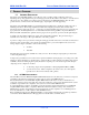
MAN-13466 REV CA CLASSIC SERIES NON-ISOLATED AMPLIFIER 1 PRODUCT OVERVIEW 1.1 GENERAL DESCRIPTION The Classic Series DIN Rail amplifier (non-isolated) provides a complete signal conditioning solution for amplifying and reporting signals from a pair of strain-gage-based load cells. Either semiconductor or foil-based load cells can be used.
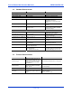
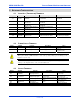
CLASSIC SERIES NON-ISOLATED AMPLIFIER 1.2 MAN-13466 REV CA GENERAL SPECIFICATIONS Item Specification Comments Power Supply Requirements 24 VDC @ 120 milliAmps Basic Non-Isolated Amplifier Power Supply Limits 20 to 28 VDC Basic Non-Isolated Amplifier Transducer Excitation (Vexc) 5.0 or 10.0 VDC Shipped with V EXC. Set at 5.0 VDC. 100milliAmp maximum. Switchable to 10 VDC with internal switch. Transducer Resistance Range 100 to 1000 Ohms Do not exceed maximum excitation current.
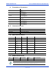
MAN-13466 REV CA 1.4 CLASSIC SERIES NON-ISOLATED AMPLIFIER ENVIRONMENTAL REQUIREMENTS Requirement Description Enclosure IP20 NEMA 1 Operating temperature 0 to 55 degrees C 32 to 132 degrees F Humidity Non-condensing 85% at 55 degrees C 85% at 132 degrees F Altitude 1000 meters 3300 feet Atmosphere Non-flammable, non-corrosive and dust free Storage temperature range -25 to 80 degrees C -13 to 176 degrees F Transport temperature range -25 to 80 degrees C -13 to 176 degrees F 1.
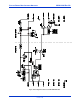
CLASSIC SERIES NON-ISOLATED AMPLIFIER MAN-13466 REV CA Figure 1 Block Diagram of Classic Series DIN RAIL MWI-13466 PAGE 8 OF 26
MAN-13466 REV CA CLASSIC SERIES NON-ISOLATED AMPLIFIER 2 SETUP AND CONFIGURATION 2.
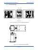
CLASSIC SERIES NON-ISOLATED AMPLIFIER Power Supply Terminals Output Terminals RECOGNITION DIAGRAMS RIGHT SIDE VIEW Transducer Terminals LEFT SIDE VIEW FRONT VIEW Figure 2– Front and Side Views of Classic Series DIN Rail Amplifier MWI-13466 Figure 3 - Classic Series DIN Rail Amplifier Mounting Diagram PAGE 10 OF 26 LOAD CELL AMPLIFIER WITH NON-ISOLATED OUPUTS CMC PART NUMBER: MWI-13466 www.CMCcontrols.com WIRING DIAGRAM 2.
MAN-13466 REV CA CLASSIC SERIES NON-ISOLATED AMPLIFIER J2 J1 Output Board J3 Input Board J10 J9 J7 P5 Coarse Zero I/A Gain Figure 4 - Internal Jumper-switches and Potentiometer Location 2.5 CONFIGURING THE SWITCH SETTINGS A number of operational characteristics can be configured prior to mounting or wiring the amplifier. We recommended that you first familiarize yourself with the internal switch locations, settings, and potentiometers by opening the snap-on access cover.
CLASSIC SERIES NON-ISOLATED AMPLIFIER 2.6 MAN-13466 REV CA POTENTIOMETERS In addition to the Gain and Zero adjustable Potentiometers visible on the front of the unit, there is an adjustment you can make by removing the snap-off cover on the side of the amplifier. The adjustment is on the input printed circuit board as shown in Figure 4.
MAN-13466 REV CA 2.9 CLASSIC SERIES NON-ISOLATED AMPLIFIER METER VOLTAGE/CURRENT CONFIGURATION The damped output for a tension indicator can be configured as either a +/- 2V output or a +/- 1mA output by changing the position of jumper-switch J1 located on the Output Card (Refer to Figure 4 for location). Voltage output is selected by setting J2 (1-2). Current output is selected when J2 (2-3 ). Note that different wiring terminals are employed for the signal return when configured for current or voltage.
CLASSIC SERIES NON-ISOLATED AMPLIFIER MAN-13466 REV CA • Do not pre-tin the stranded wires inserted into the pluggable connector. • A stable connection relies on the springy nature of stranded conductors to ensure a low contact resistance despite thermal cycling and airborne impurities. • Avoid temperature extremes or gradients where electrical connections are made between different metals.
MAN-13466 REV CA CLASSIC SERIES NON-ISOLATED AMPLIFIER 2.12.2 OUTPUT WIRING 1 2 3 4 5 6 7 8 + / - 10V LOAD 5000 OHM MIN RESISTANCE + SHIELD GND 1 2 3 4 5 6 7 8 The load in this connection may be an indicator, recorder, data acquisition device or the analog input terminals of a control device such as a DC drive or a programmable logic controller. The output signal at this terminal is undamped and is the output terminal that provides that fastest response to changes in the transducer (load-cell) load.
CLASSIC SERIES NON-ISOLATED AMPLIFIER MAN-13466 REV CA 2.12.2.2 DAMPED +/- 1 MA ANALOG The meter output stage can be configured to operate as current output (sinking or sourcing current depending upon output polarity). It can be used concurrently with the +/-10V output. It does not have an individual Gain and Zero adjustment, necessitating that a compromise be made during calibration, or a particular output be favored (over one that can accommodate external scaling and offsetting).
MAN-13466 REV CA 3.1.2 CLASSIC SERIES NON-ISOLATED AMPLIFIER POWER APPLICATION Apply DC power to the amplifier and use a DC voltmeter to confirm that the supply polarity and voltage is within the prescribed limits. As soon as is practical, confirm that the excitation voltage is either 5.0 VDC or 10.0 VDC as appropriate for the type of load cells being used. Promptly identifying any over-voltage condition can help minimize potential damage to the strain gage elements internal to the transducer.
CLASSIC SERIES NON-ISOLATED AMPLIFIER 3.4 MAN-13466 REV CA CHECKING TRANSDUCER MOUNTING Before preparing to apply force to the transducer(s) and calibrating the amplifier you should check to be sure that the load cell is orientated and mounted in accordance to the transducer installation instructions. Common problems include: • Failure to orient the transducer on a flat (machined) surface. • Poor shaft alignment that exceeds allowable limits. • Excessive or insufficient fastener torque.
MAN-13466 REV CA 3.5 CLASSIC SERIES NON-ISOLATED AMPLIFIER ACCURACY CONSIDERATIONS The application of an accurate calibration force requires careful attention to minimizing the non-ideal affects of the real world. Keep the following points in mind: • Allow the transducer and amplifier to reach thermal equilibrium before conducting calibration. Ideally, the temperature should reflect the expected operating conditions.
CLASSIC SERIES NON-ISOLATED AMPLIFIER 3.6 MAN-13466 REV CA PROPER PRACTICES FOR APPLYING CALIBRATION FORCES Seldom is a transducer oriented such that the calibration can be done by simply hanging a true dead weight from the roll. By generating a tension force that follows the same web path across the roll, you avoid the necessity of making manual (numerical) calculations to correct for the details of different wrap angle, transducer orientation, etc.
MAN-13466 REV CA CLASSIC SERIES NON-ISOLATED AMPLIFIER Examples of Force Loss due to Friction at Driven Roll In this example, by rearranging the anchor point and the force location as well as utilizing the idle roll, the frictional losses are minimized. In this example, only a fraction of the test force is transferred to the transducer due to drag from the driven roll. 3.7 ADJUSTMENT TOOLS Using the correct tools simplifies making the necessary adjustments during the setup procedure.
CLASSIC SERIES NON-ISOLATED AMPLIFIER 3.8 MAN-13466 REV CA ADJUSTING AMPLIFIER COARSE ZERO A coarse offset adjustment has been provided. Keep in mind that the Coarse Zero adjustment is usually only adjusted one time, typically when the amplifier is installed, or transducers are replaced. 1. Ensure that the IA gain setting has been set as described in section 2.5. 2. Set the Zero pot on the front cover to mid-way (approximately 9 turns from either clutch actuation). 3.
MAN-13466 REV CA 3.10 CLASSIC SERIES NON-ISOLATED AMPLIFIER EMC CONNECTIONS AND INSTALLATION GROUND 0 TO 10V LOAD 5000 OHM MIN RESISTANCE GROUND BRAIDED SHIELD CONNECTED TO GROUND WITH 360 DEGREE BONDS ON EACH END.
CLASSIC SERIES NON-ISOLATED AMPLIFIER MAN-13466 REV CA Appendix A. MANUFACTURERS DECLARATION OF CONFORMITY Number: AO-90311 Manufacturer: Cleveland Motion Controls, Inc. 7550 Hub Parkway Cleveland, Ohio 44125 U.S.A.
MAN-13466 REV CA CLASSIC SERIES NON-ISOLATED AMPLIFIER Appendix B. CABLE GLANDS Several manufacturers provide cable glands that can be used to ensure the integrity of the EMC requirements when installing this equipment in the enclosure. The objective of the cable gland is to provide a good mechanical entry into the enclosure to protect the cable and also provide an electrical bond the outer shield (screen) of the cable to the enclosure.
CLASSIC SERIES NON-ISOLATED AMPLIFIER BLANK PAGE 26 OF 26 MAN-13466 REV CA