CLEVELAND-KIDDER® UNDER PILLOW BLOCK WASHDOWN-DUTY LOAD CELL INSTRUCTION MANUAL . . . TYPE UPB WASHDOWN-DUTY 7550 Hub Parkway Cleveland, Oh 44125-5794 Phone: 216-524-8800 Or 800-321-8072 Fax: 216-642-2100 Visit Us: www.cmccontrols.
1.0 GENERAL INFORMATION Critical roll = 4.8 x 10⁶ x Shaft O.D. speed in RPM (Shaft Length)2 1.1 Dimensions are in inches. RECEIVING AND UNPACKING Handle and unpack the equipment carefully. Immediately upon arrival, check the shipment against the packing list. Any damage should be reported immediately to the carrier and to the nearest CMC representative. Equipment that will not be installed immediately should be stored in a clean, dry location.
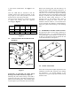
1.4 DESCRIPTION The Cleveland-Kidder Washdown Duty UPB transducers utilize a sensing twin beam to which semiconductor strain gages are bonded. With these high output signal gages a very small force on the sensing beam will be shown as a change in the tension signal. Pillow Block Bearing The type UPB transducers are for use with shafts that are mounted in Pillow Block Bearings. See Figure 1. For mounting dimensions see Figure 2.
2.0 INSTALLATION 2.1 PRECAUTION Always install, orient and firmly bolt down the transducers BEFORE installing the tension-sensing roll. When disassembling or installing, DO NOT remove the transducer and the tensionsensing roll as an assembly - remove the roll first, before loosening the transducer mounting bolts. SELECTION OF TRANSDUCER MOUNTING LOCATION When selecting a transducer mounting location, keep in mind that the tension-sensing roll must NOT be mounted where the web wrap angle can vary.
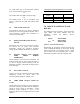
a good tension measurement. See Figure 4 for details. Note: the UPB must be oriented so that the resultant tension force direction (bisector of the wrap angle) is in the same quadrant as the load direction arrow on the side of the UPB. Once the correct orientation is selected, you need to tighten four locking bolts (not supplied) accordingly to Figure 5. UPB 1 2 3 English Metric Length Torque Length Torque min. (in.) (ft.-lbs.) min. (mm) (N-m) 1.00 10 25 15 1.50 30 40 40 2.50 150 65 200 Figure 5 2.
3.0 ELECTRICAL CONNECTION EXCITATION VOLTAGE (-) BLK B WHT A (+) RED TENSION GAGE TEMP. COMPENSATION NETWORK NO. 1 TRANSDUCER C 4.0 BLK (-) WHT TENSION GAGE B A TEMP. COMPENSATION NETWORK (+) RED C NO. 2 TRANSDUCER COMPRESSION GAGE WIRING DIAGRAM FOR TRANSDUCERS Figure 8 Refer to the installation wiring diagrams supplied with the Cleveland-Kidder tension indicator or controller for making the transducer connections.
not weigh more than ½ the maximum working force of the transducers in most cases. Or The surface under the UPB is not flat enough. Or The bolting torque is not in accordance with Figure 5 (especially for UPB with MWF under 250 lb.). 6.2 LOW OUTPUT SIGNAL The transducer may have too large a maximum working force for the application. Replace with a lower maximum working force transducer or increase web wrap angle. 6.3 WRONG POLARITY OF OUTPUT SIGNAL Transducers may have been incorrectly oriented.
Note: Consult CMC for assistance in sizing the load cell to your specific application. 8.0 USEFUL SPECIFICATIONS 8.1 WEIGHT Weight lb. (kg.) Each UPB 1 UPB 2 UPB 3 Complete 3.7 (1.7) Unit Without 1.5 (0.7) mounting plate 8.2 A 22 (10) 102 (47) 12 (5.4) 59 (27) A/2 T C RATINGS L RATING (LB) * ULTIMATE OVERLOAD (%) UPB 1 25 to 1000 500 UPB 2 1000 to 10000 20000 500 250 UPB 3 10000 to 30000 500 8.
LIMITED WARRANTY. ALL GOODS ARE SOLD SUBJECT TO THE MUTUAL AGREEMENT THAT THEY ARE WARRANTED BY THE COMPANY TO BE FREE FROM DEFECTS IN MATERIAL AND WORKMANSHIP FOR ONE YEAR FROM THE DATE OF SHIPMENT.