
Manual


INSTRUCTION NUMBER: AO-70136 BA 2 of 9
1.0 GENERAL INFORMATION
1.1 RECEIVING AND UNPACKING
Handle and unpack the equipment carefully.
Immediately upon arrival, check the shipment against
the packing list. Any damage should be reported
immediately to the carrier and to the nearest CMC
representative.
Equipment that will not be installed immediately
should be stored in a clean, dry location. Precautions
should be taken to prevent moisture, dust and dirt
from accumulating in storage and installation areas
1.2 PRECAUTIONS
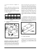
1.2.1 Shipping
- It is recommended that the sensing
roll be removed when the machine is shipped with the
transducers mounted. The shock and vibration
transmitted to the transducers by the sensing roll
during transporting can damage them.
1.2.2 Roll Balance
- The sensing roll should be
balanced to prevent forces caused by imbalance.
These forces cause a noise signal to be superimposed
on the tension signal. The centrifugal force (F) caused
by imbalance can be calculated using the equation
below.
F = 28.6 x 10
-6
x W x R x (RPM)
2
Lbs.
W = Weight of roll in pounds
R = Displacement of mass of roll from the
axis of rotation in inches
RPM = Revolution per minute
It is recommended that the force (F) be less than 5%
of the resultant web force at the maximum web speed
for most applications.
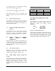
1.2.3 Critical Roll Speed
- Even with a balanced roll, a
vibration can be set up in a stationary shaft. If this
vibration (in cycles per minute) occurs at the
harmonic frequency of the shaft, the transducers can
be damaged. To determine the critical roll speed, use
the following formula:
Critical roll = 4.8 x 10
6
x Shaft O.D.
speed in RPM (Shaft Length)
2
Dimensions are in inches.
To assure that this problem is avoided, the critical roll
speed should at least be 20% above the roll speed
attained at maximum web speed.
1.2.4 Overloading
- Repetitive overloading above the
maximum working force or severe overloading should
be avoided because it will damage the transducers.
1.3 SPECIFICATIONS
Gage Resistance - End to end resistance 440-480
Ohms
Gage Factor - 100 nominal
Excitation Voltage -10 VDC or VAC (RMS)
maximum
Output Signal
at Rated MWF - 100 mV nominal per
Transducer (1/2 bridge)
200 mV nominal per
Transducer pair (full bridge)
Output Impedance - Approximately 880 Ohms for
UPB2 and UPB3
Approximately 120 for UPB 1
Required Input
Impedance of
Tension Amplifier - 5K ohms per Transducer (1/2
bridge)
Maximum Voltage,
Gage to Beam or
Base (Ground) - 50 VDC
Operating
Temperature Range - 0
F to +200
F
Compliant