
Manual


INSTRUCTION NUMBER: AO-70136 BA 6of 9
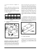
3.0 ELECTRICAL CONNECTION
Figure 8
Refer to the installation wiring diagrams supplied
with the Cleveland-Kidder tension indicator or
controller for making the transducer connections.
Make certain that the cables do not interfere with
the web path and that they are away from gearing
or other moving parts.
Many of the Cleveland-Kidder indicators and
controllers use only half bridge transducer inputs
and then sum the two transducer signals internally.
See the applicable installation wiring diagrams for
the tension indicator or controller.
3.1 MATING CONNECTORS FOR
TRANSDUCERS
USE CMC P/N
Mating Straight Connector,
Boot and Clamp Kit MO-09854
Mating 90
Angle Connector,
Boot and Clamp Kit MO-09855
These are not sealed for washdown duty. For
washdown duty mating connector consult CMC.
3.2 INTRINSICALLY SAFE
TRANSDUCERS
These transducers are intrinsically safe only when
they are part of a complete intrinsically safe
system using the TIX-1 tension indicator or wired
per CMC control drawings.
Barrier block assemblies and/or the individual
barrier blocks may be purchased from CMC. Please
contact CMC for part numbers and pricing.
4.0 TEMPERATURE
COMPENSATION
The transducers are supplied with a temperature
compensation network (except size 1 which don’t
require it) which is in series with the output signal
lead. The compensation circuit is designed to be
used with a tension amplifier which has an input
impedance of 10K Ohms when a pair of transducers
connected as a full bridge is used. If only one
transducer is used, the tension amplifier impedance
should be 5K Ohms. If other than the input
impedances given above are used, drift will occur
in the tension amplifier output when the transducer
temperature changes.
5.0 SINGLE TRANSDUCER
OPERATION
For those applications where only one transducer is
required, a dummy circuit may or may not be
required depending upon the input circuit of the
tension amplifier. Consult the factory for this
information. The dummy circuit consisting of two
resistors is substituted in place of the second
transducer. The resistors should have a resistance
value between 100 and 150 Ohms and should be
matched to within 1%. Dummy circuits are
available from the factory for connecting to tension
indicators or controllers.
6.0 TROUBLESHOOTING
6.1 EXCESSIVE OUTPUT SIGNAL
WITH NO LOAD
There may be a high degree of misalignment of the
transducers causing a severe pre-load.
Or
The sensing guide roll assembly may be
excessively heavy. The sensing guide roll should
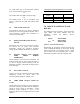
BLK
WHT
SHIELD
BLK
WHT
RED
EXCITATION
VOLTAGE
OUTPUT
SIGNAL
(-)
(-)
(+)
(+)
B
C
A
TENSION GAGE
COMPRESSION GAGE
TEMP. COMPENSATION
NETWORK
NO. 1
TRANSDUCER
COMPRESSION GAGE
TEMP. COMPENSATION
NETWORK
C
A
TENSION GAGE
B
NO. 2
TRANSDUCER
WIRING DIAGRAM FOR TRANSDUCERS
RED