Cleveland Motion Controls QUANTUM USER MANUAL MAN-70421
TENSION CONTROL Congratulations on your Cleveland Motion Controls Quantum digital controller! You have just acquired the most user friendly and powerful digital controller in its category. This user manual has been designed to give you all the information you need for installation and commissioning.
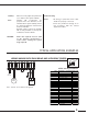
DIMENSIONS - FIXING 166 4 111 38 1 - 5 mm 100 2 15 156 101 Front panel cutout BASIC WIRING +24 Com output control logic inputs alarms Primary Supply fuse 3.
OVERVIEW User friendly Selectable language (En / Fr / Ge / It) Selectable Metric or Imperial units HOLD and RELEASE on front panel keyboard Advanced regulation capabilities Automatic P.I.D.
Stability: When necessary adjust the parameters (*) to improve the system stability Troubleshooting Note: Variable PID (coefficients are proportional to the diameter) is also available when system stability cannot be obtained (diameter measurement must be available).
UNWIND WITH LOAD CELLS AND EMAG BRAKE Wiring +5V S1+ Com S1- Reg Init V+ B A V+ C2 C1 +24 Com CLOSED LOOP Other load c e l l s configuratios, see page 9 * Initial set of parameters File : Force_feedback.prm 0 10 100 100 (*) 20 (*) 0 100 (*) 0 100 0 Jumpers Logic input B N.O.
UNWIND WITH MOTOR AND LOAD CELLS Wiring +5V S1+ Com S1- DM Com TC Com AO1 Com Reg Init V+ B A V+ +24 Com CLOSED LOOP Logic input B N.O. Drive Output -10 - +10V Web rotation Load cell Classic Tachometer 0 - 10V R BK WH R BK Diam. Input 0 - 10V WH Jumpers +24 V AC / DC Load cell Classic Note : all Com / 0V are linked to the ground Initial set of parameters File : Force_motor.
+5V S1+ Wiring Com S1- DM Com TC Com AO2 Com Reg Init V+ B A V+ C2 C1 +24 CLOSED LOOP Com REWIND WITH LOAD CELL + CLUTCH/MOTOR EMAG Brake Logic input B N.O.
+5V S1+ S1- +5V S1+ Com BLK BRN V One Load Cell Full-Bridge Ultra- Series Load cell Classic Two Load Cells Half-Bridge Classic - Series 0 + Full bridge Load cell Ultra V - 0 +5V S1+ BRN BLK Com BLU WH BRN BLK WH Load cell Classic BLU R WH BK R WH BK S1- +5V S1+ One Load Cell Half-Bridge Classic - Series Com + 0 Full bridge Load cell Ultra Load cell Classic S1- BLU - R BK WH WH 10 kΩ 10 kΩ S1- Com OTHER LOAD CELL CONFIGURATIONS Wiring + V Full bridge
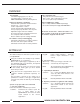
KEYPAD BASICS 1 – SET POINT Setting 2 – Variable Setting Hold for increase Ent • Press both buttons simultaneously to enter the Data field (visible underscore) Hold for decrease • Press once to increase/decrease one digit Escape from Setting mode Esc • Press to validate each digit • Last digit validation sends the complete value to the system (underscore disapears) 4 – System General Settings Initial readout Ent ------------------------------- RECALL MEMORY Ent M1 Ent MEMORY READ Esc M2
display inputs regulation type functions outputs memories regulation type open loop basic PID variable PID inputs measure set point diameter tachymeter display language units display config. 0 0 0 P (proportional) I (Integral) D (derivative) loop coeff max Diam. coeff. min Diam. coeff. loop coeff. 1 0 max. effort filtering 7 7 8 7 0.1 9 0.
www.cmccontrols.com memories save call outputs thresholds AO2 readout logical outputs power output functions time delay start time delay stop E-stop option no-stop hold taper 1 duration (* 10ms) M1 M2 M3 M4 M5 gain AL1 : error range AL2 : Diam. limit set point measure diameter rotation speed 3 3 8 10 1 100 0 13 3 3 10.0 12 0.
PC SOFTWARE - INSTALLATION AND USE The CD-Rom delivered with your box contains a PC software dedicated to the QUANTUM, called QUANTUMsoft. Launch the “Setup” file to automatically install the software on your PC in: “C:\ProgramFiles\cmc\quantum\” During the installation process, a shortcut is automatically created in Run\Programs The application is launched by a double click on the icon.
NOTES 14 www.cmccontrols.
1.0 Parameter 1.1 Communicate parameters to regulator Save or load a set of parameters on the PC To save a set of parameters, click in the thumb index 'file' then choose 'save as…' for recording in a new file (file..PRM.), or 'recording' to record the set of parameters in the file in progress. To open a set of parameters, click in menu 'file', then choose 'open…'. The set of parameters will automatically load in the right interface.
Parameter 1.2 Begin a new parameter setting Choose the type of parameter setting Before beginning a new parameter setting, you must select the application type: Click in menu 'Parameter,' or in the thumb index 'Parameter' then 'New,' choose your application. -Open loop Tension control application by measurement of the diameter Inertia compensation with analogical line speed information -Closed loop Tension control application by measurement of the tension or the torque.
2.0 Menu INPUTS 2.1 Measure Menu This menu appears when choosing closed loop, inertia correction,motor command or speed follower. It allows calibration for any type of measurement, from a few mV to 10V. Measure calibration % full scale: Type in the percentage of full scale corresponding to the upper point used during calibration (this percentage must be more than 20%). Valid high level: Type in the value for the upper point. Valid low level: Type in the value for the lower point.
Menu INPUTS 2.2 Set Point Menu Two types of set points are available -Internal set point: type in the chosen value, it can be modified by the operator with the arrows on the keyboard. A ramp can be used for soft start. The ramp is activated when the switch Regulator is turned on. -External 0-10V set point: Potentiometer or PLC connected to "set point" pin. The set point unit is given in menu DISPLAY. Open loop case: In this case, the parameter Max Effort must be given.
Menu INPUTS 2.3 Diameter Menu Diameter calibration With an analog diameter measure, the signal must be calibrated from physical values (upper point = max diameter, lower point = min diameter). Valid max diameter: Type in the max diameter value. Valid min diameter: Type in the min diameter value. The diameter unit is chosen in the DISPLAY menu.
Menu INPUTS 2.2 FILTERING All the inputs can be filtered. Filtering makes the regulation less sensitive to electric and mechanical disturbances but generates a delay in the system response time. A few rules: Measure : Filtering depends on the application and product. Converting force from 100. Converting force on elastic product from 400. Dancer from 0. Set point: Useful for external set point to filter the signal or simulate a ramp.
3.0 Menu DISPLAY 3.1 Units / Display The front panel is used to display measurement values as well as different data used by the Controller. These two menus (Units / Display) have to be used to choose what will be displayed on the two available16 digits lines. Units This menu is used to choose the units for the measurement and for the diameter values. Display This menu is used to choose what information will be displayed on the two lines.
4.0 Menu FUNCTION 4.1 E-STOP function Principle The E-stop function could be used for the Emergency stop or for any other particular process. Two different options are available: Fixed E-Stop value and Proportional E-Stop value. The last one sends an output voltage related to the last current output (before switching to the HOLD mode) How does it work Fixed HOLD value: by entering a value between 0 - 100% , a proportional value between 010V will be sent on the output (i.e.
Menu FUNCTION 4.2 Time Delay Menu Principle When the machine process management (motor start and stop) is not synchronized with the controller logical inputs remote control (external switches Reg and B), some regulation troubles can appear. The synchronizing problems can be solved with the time delay options available in the Controller functions.
Menu FUNCTION 4.3 HOLD function Principle The Hold function can be used by the operator for the machine settings (out of regulation mode). It allows the operator to directly manage a constant ouptut voltage level (parameter always available on the controller front panel).
Menu FUNCTION 4.4 Inertia This menu is available for open loop configuration when inertia compensation is required. Inertia compensation function The inertia compensation function allows the controller to increase or decrease the output during the acceleration/deceleration periods. This coefficient (inertia gain) is related to the roll inertia (proportional to the actual diameter measurement) and to the actual line speed (tachometer input).
Menu FUNCTION 4.5 NO-STOP function Principle This function is used to manage two independent outputs (one which is the calculation result output and the second one which is fixed - hold value). This is usually very useful to manage the automatic splice turrets systems. How does it work Click in the "No-Stop" special function box to enable the function.
5.0 Menu PID 5.1 Coefficients Menu This menu is available for both closed loop and inertia compensation configurations. 5.2 Closed loop + Open loop Control function When using a closed loop configuration, this function allows integration with an open loop control by using a specific coefficient for each of these control modes; open loop gain and closed loop gain.
5.0 Menu PID 5.4 PID Menu Principle The P.I.D. is the heart of the controller calculation system when using the Closed loop mode. P , I , and D parameters are the coefficients which give the actual output result from the Measurement - Set point difference . CAUTION : the PID calculation must be disabled during the machine rest periods to avoid that a static Measurement - Set point difference increases the output value to the maximum (giving a very high overshoot for the next machine restart) .
5.0 Menu PID 5.5 Motor This menu is available in motor command configuration. Tension control for motorized rewinder in speed regulation. In this case, we need linear speed (tacho) and diameter information to calculate the rotation speed of the motor.
6.0 Menu OUTPUTS 6.1 Working range Principle This function defines the two limits for the actual regulation voltage output AO1 (or AO1 and AO2 when using the No-Stop mode) inside the global output range (-10 / + 10 V). Useful function when using the controller with a device which only uses 0 - +10V input. How does it work Min. threshold: Means the minimum voltage allowed to the controller regulated output (enter the threshold value between -10V et +10V). Max.
Menu OUTPUTS 6.
Menu OUTPUTS 6.3 Current limitation Principle This function limits the current in the coil when using EMAG brakes and EMAG clutches directly. As the supply of the coil is done by a pulse width modulation on the rectified supply of the QUANTUM, the parameter drives the duty cycle of the PWM. How does it work Enter a value between 1-100% corresponding to the maximum current for the application.
Menu OUTPUTS 6.4 ALARM management function Principle Two digital outputs have been designed to provide two different alarm signals: Regulation fault: When the Measurement - Set point difference is over the pre-set tolerance, it means that there is something wrong in the process. Min. Diameter: Diameter measurement threshold available to alert the operator before the real end of the bobbin.
7.0 Digital Inputs 7.1 Digital Inputs A and B Principle The digital inputs A and B are dedicated to the management of the controller’s global status. It provides the user the ability to create an automatic relationship between the machine process and the controller status (i.e. to manage the E-Stop needs).
Digital Inputs 7.2 Logical inputs Reg and Init Principle The digital inputs Reg and Init are dedicated to the management of the P.I.D. calculation process.
8.0 Data Capture 8.1 DATA CAPTURE Menu Starting a Data Capture The PC software includes a Data capture function, allowing to visualize and to record each Controller input/output actual value/status, four times/sec. To start a data capture, go to the REGULATOR / Start Acquisition option. To record the data on the computer, enter a new File name (ext., .acq). The data capture will start and the data will be saved in the related file. To look at the data without recording, choose ‘Cancel.
7550 HUB PARKWAY CLEVELAND, OH 44125 216.524.8800 or 800.321.8072 www.cmccontrols.