INSTRUCTION MANUAL (MAN-70252) CLEVELAND-KIDDER ® ULTRA CANTILEVER TRANSDUCER MODELS: CLTEC, CLTSC, CLTECM & CLTSCM REVISION AA Industrial Products Division 7550 Hub Parkway Cleveland, Ohio 44125 Phone: 216.524.8800 Fax: 216.642.2131 www.CMCcontrols.
ULTRA SERIES CANTILEVER TRANSDUCER MAN-70252 REV.
MAN-70252REV. AA ULTRA SERIES CANTILEVER TRANSDUCER TABLE OF CONTENTS 1 IMPORTANT INFORMATION .........................................................................5 1.1 ORDER NUMBERS ........................................................................................................... 5 1.2 CONTACT INFORMATION AND SERVICE ASSISTANCE .......................................................... 6 1.3 RECEIVING AND UNPACKING .............................................................................
ULTRA SERIES CANTILEVER TRANSDUCER MAN-70252 REV. AA WARRANTY Cleveland Motion Controls warrants the goods against defects in design, materials and workmanship for the period of 12 months from the date of delivery on the terms detailed in the Cleveland Motion Controls, Inc. Terms and Conditions of Sale, document number AO-90131 Cleveland Motion Controls, Inc. reserves the right to change the content and product specification without notice.
ULTRA SERIES CANTILEVER TRANSDUCER MAN-70252REV. AA 1 IMPORTANT INFORMATION 1.1 ORDER NUMBERS Use the following example and Tables A, B and C to determine order numbers for: • Ultra Series Transducers • Mounting Kits • Shaft Adapter Figure 1 – Example for Determining Transducer, Mounting Kit and Shaft Adapter Order Numbers If you needed to Purchase a Transducer, Mounting Kit and Shaft Adapter corresponding to following description: Then, you would use Catalog Numbers: • Size 2 cartridge body.
ULTRA SERIES CANTILEVER TRANSDUCER MAN-70252 REV.
ULTRA SERIES CANTILEVER TRANSDUCER MAN-70252REV. AA 1.4 PRE-INSTALLATION PRECAUTIONS 1.4.1 SHIPPING Shock and the vibration transmitted to the transducers by the sensing roll during transportation can damage the transducers. It is essential that you remove the sensing roll when the machine is shipped with the transducers mounted. 1.4.2 ROLL BALANCE The sensing roll should be adequately balanced.
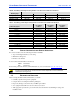
ULTRA SERIES CANTILEVER TRANSDUCER MAN-70252 REV. AA 2 SPECIFICATIONS Item: Specification: 1T ALUM 1T STEEL 2T STEEL 1.9 lbs. 0.86 kg. 2.7 lb. 1.23 kg 3.7 lb. 1.68 kg 1T ALUM 1T STEEL 2T STEEL Flange 2.9 lbs. 1.32 kg. 3.7 lbs. 1.68 kg Bearing 2.3 lbs. 1.05 kg. 4.8 lbs 2.18 kg. 3.1 lbs. 1.41 kg. 5.6 lbs. 2.54 kg. 5.3 lbs. 2.41 kg 4.2 lbs. 1.91 kg. 7.9 lbs. 3.59 kg.
ULTRA SERIES CANTILEVER TRANSDUCER MAN-70252REV. AA 2.1 FORCE RATINGS Refer to Table A in this document for Transducer Maximum Working Force Ratings. 2.2 BEFORE INSTALLING THE TRANSDUCER Before installing the Transducer, perform the following steps: 1. Review the Installation Precautions (Section 2.2.1 on page 9). 2. Review the Safety Considerations (Section 2.2.2 on page 9) 3. Review the Mounting Configurations (Section 2.2.3 on page 10) 4.
ULTRA SERIES CANTILEVER TRANSDUCER 2.2.3 MAN-70252 REV. AA MOUNTING CONFIGURATIONS Ultra Series Cantilever Transducers can be mounted on either the inside or outside of the machine depending on the model type purchased (refer to Figure 1 and Table D).
ULTRA SERIES CANTILEVER TRANSDUCER MAN-70252REV. AA 2.2.4 MOUNTING HARDWARE AND FASTENER TORQUE RECOMMENDATIONS The Table E provides you with guidelines to refer to when determining torque values for clean and dry fasteners. Keep in mind, however, that several variables can influence the “optimum” torque to be used in a given situation, and Table E should be used only as a general reference.
ULTRA SERIES CANTILEVER TRANSDUCER 2.2.5 MAN-70252 REV. AA MOUNTING DIMENSIONS L F L V R (MAX) P C O I C 45 DEG K K A A H E (MAX) J J TYPE CLTEC and CLTECM Cartridge with BR Mounting Kit TYPE CLTSC and CLTSCM Cartridge with FL Mounting Kit L V F L C B (MAX) M (BOLT DIA) N (B.C.D) F A Z K D K A H U T W/2 J W Type CLTSC and CLTSCM Cartridge Mounting dimensions in Inches: CLTEC and CLTSC Designator: 1T 2T A Per Adapter Per Adapter B 0.55 0.60 C 2.50 2.75 D 1/2-13 5/8-11 E 2.
ULTRA SERIES CANTILEVER TRANSDUCER MAN-70252REV. AA 3 INSTALLING THE CANTILEVERED TRANSDUCER The following sections provide you with detailed information and steps to correctly install the Ultra Series Cantilevered Transducer for use with stationary shafts. 3.1 MOUNTING THE TRANSDUCER The mounting surfaces for the transducer should be flat. Remove any loose paint, rust or scale from the machine frame before mounting.
ULTRA SERIES CANTILEVER TRANSDUCER 3.2 MAN-70252 REV. AA MOUNTING THE SENSING ROLL The following steps take into consideration the risk and difficulty of handling large rolls and help to minimize the number of failed attempts at mounting the roll. 1. Before mounting the sensing roll, confirm that the transducer body is securely mounted. 2. Measure the roll shaft diameter, the shaft adapter bore diameter to be sure that they fit properly. 3. Loosen the two (2) set screws on the shaft adapter. 4.
ULTRA SERIES CANTILEVER TRANSDUCER MAN-70252REV. AA 3.4 CHECKING THE TRANSDUCER MOUNTING Before preparing to apply force to the transducer and calibrating the amplifier, inspect the load cell to confirm that it is oriented and mounted in accordance to the installation instructions. Common problems include: • Failure to mount transducer on flat (machined) surface. • Shaft length or roll weight that exceeds allowable limits. • Fastener torque either excessive or insufficient.
ULTRA SERIES CANTILEVER TRANSDUCER Pin Number 1 2 3 4 Wire Color brown white blue black Signal Excitation Voltage Output - (low going) Excitation Return Output + (high going) If you choose to make your own cables or need to repair damaged connectors, you can purchase a separate mating connector from Cleveland Motion Controls. To order, use CMC part number, X44-34338. MAN-70252 REV.
MAN-70252REV. AA ULTRA SERIES CANTILEVER TRANSDUCER 4 TROUBLE SHOOTING Safety should not be an afterthought. Before installing, servicing or calibrating review and follow applicable policies and procedures to ensure worker safety. Machinery must be in a safe state and be aware of any additional hazards that can arise when installing and calibrating higher force transducers.
ULTRA SERIES CANTILEVER TRANSDUCER 4.1 MAN-70252 REV. AA DC RESISTANCE CHECK If you have attempted to resolve your issue using the table above and have been unsuccessful, use the following checks to determine the viability of the transducer. The following nominal DC resistances table indicates a normal load cell, with no load applied at room temperature. The resistances are cited using both the wire color and the M12 connector pin numbers (Figure 7).