
Manual


MAN-70252REV. AA ULTRA SERIES CANTILEVER TRANSDUCER
PAGE 15 OF 18
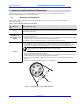
3.4 CHECKING THE TRANSDUCER MOUNTING
Before preparing to apply force to the transducer and calibrating the amplifier, inspect the load cell to confirm that it
is oriented and mounted in accordance to the installation instructions. Common problems include:
• Failure to mount transducer on flat (machined) surface.
• Shaft length or roll weight that exceeds allowable limits.
• Fastener torque either excessive or insufficient.
• Transducer mis-oriented so that the axis of sensing is not true to the applied force vector (bisector of
the wrap angle).
• The transducer is positioned in the web path so that the wrap angel is not constant.
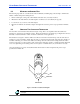
3.5 ELECTRICAL CONNECTIONS AND WIRING
Refer to the installation wiring diagrams supplied with the Cleveland-Kidder tension indicator or controller for
making the transducer to amplifier connections. Make certain that:
• The cables do not interfere with the web path, and that they are away from gearing or other moving
parts.
• You exercise care when routing the cables to avoid pick-up from noise-radiating power cabling (motor
armature leads, AC main wiring, etc).
• In environments with severe electromagnetic noise, it may be necessary to route the cables inside
metallic conduit.
• Polarity changes are accommodated by reversing the orientation of the transducer or by interchanging
the black and white output wires.
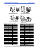
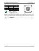
Figure 6 illustrates a typical full bridge transducer configuration.
LEFT XDCR
8
7
6
3
4
5
2
1
1
2
3
BLK
WHT
BLU
BRN
6
5
4
8
7
WHT
BLU
BLK
BRN
1
1
2
3
4
2
3
4
RIGHT XDCR
CT
TC
CT
TC
Figure 6 – Full Bridge Transducer Wiring
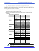
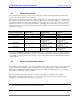
3.6 MATING CONNECTORS
The M12 connector used on the Ultra Series Cantilever transducer is a four-pin, DC keyed, male connector that
mates directly with the molded cord sets offered by Cleveland Motion Controls. The following table lists the pin
numbers and cable colors that apply: