
Manual


ULTRA SERIES CANTILEVER TRANSDUCER MAN-70252 REV. AA
PAGE 18 OF 18
4.1 DC RESISTANCE CHECK
If you have attempted to resolve your issue using the table above and have been unsuccessful, use the following
checks to determine the viability of the transducer.
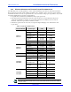
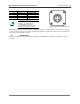
The following nominal DC resistances table indicates a normal load cell, with no load applied at room temperature.
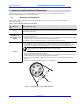
The resistances are cited using both the wire color and the M12 connector pin numbers (Figure 7). Often, it is best
to begin by measuring the resistances at the amplifier end of the cable. Then, if a problem is indicated, un-mate the
transducer end of the connector and check the resistances. Following this procedure, allows you to readily and
initially check the resistances without disturbing the transducer or M12 connections and inadvertently disturbing the
interconnect condition.
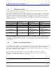
Measurements taken
between the following wires:
Corresponding M12
Connector Pins:
Target Resistance
Aluminum Beam
Target Resistance
Steel Beam
WHT - BRN 1-2 88 Ohm 88 Ohm
BLK - BRN 1-4 88 Ohm 88 Ohm
WHT - BLK 2-4 118 Ohm 118 Ohm
WHT - BLU 2-3
104 Ohm (Varies slightly
based on load cell
temperature)
112 Ohm (Varies slightly
based on load cell
temperature)
WHT - BLU 2-3
104 Ohm (Varies slightly
based on load cell
temperature)
112 Ohm (Varies slightly
based on load cell
temperature)
BRN - BLU 1-3
133 Ohm (Varies slightly
based on load cell
temperature)
141 Ohm (Varies slightly
based on load cell
temperature)
Resistance should NOT be indicated (> 10 M-ohm) between any of the transducer connections and the metal body
of the transducer when the M12 transducer connector is un-mated. A low resistance indicates a possible breakdown
of an insulation component, and could be caused by excessive voltage between the body and electrical connections
of the transducer.
4.2 DC VOLTAGE AND CURRENT CHECKS
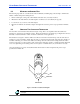
When 5VDC excitation is applied to a correctly wired transducer, the output to ground voltage for each of the bridge
outputs should be approximately 2.8 VDC. The difference in voltage between the two output leads (BLK and
WHT) is the un-amplified tension signal. It should be only tens of millivolts with little applied force, increasing to
approximately 350 mV at the transducers MWF.
The current flow through the bridge Excitation connections (into BRN and out the BLU wire) should be
approximately 35 mA and equal in each wire. Non-equal currents indicate that the current is being diverted,
indicating a potential wiring error, short circuit, or ground loop.
Trademark Information
Cleveland - Kidder is a registered trademark of Cleveland Motion Controls.