MOTOR POWERED UNWIND TENSION CONTROLLER MWP – 12662 - 1 Instruction Manual AO-70172 (Rev BA)
Blank
Table Of Contents General Description ............................................................................................................. 4 Motor Powered Unwind System ...........................................................................................................4 Quickstart ............................................................................................................................. 5 Installation .......................................................................
Table Of Contents Controller Tuning - Torque mode...................................................................................... 18 Output Level Limit...............................................................................................................................18 Static Friction ......................................................................................................................................18 Dynamic Friction .......................................................
WebPro Motor Powered Unwind Tension Controller General Description The WebPro Digital Tension Controller is part of a closed loop tension control system with transducer feedback. The Controller continuously controls the web tension to the TENSION SET POINT value and displays the true web tension on an LCD screen, either as a percentage or in engineering units. The screen will display the tension applied to each transducer separately by pressing the < LEFT tension or > RIGHT tension key.
WebPro Motor Powered Unwind Tension Controller Quickstart The Controller is supplied with the software loaded for the application as ordered but it will require commissioning before use. For more detailed information refer to the various sections later in this manual. 1. Carefully unpack the Controller, remove the rear cover and detach the bag containing the accessories. Attach the cable gland to the large hole in the rear cover.
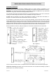
WebPro Motor Powered Unwind Tension Controller Installation The following parts are supplied: 1. Controller, with software loaded for the application but requiring commissioning by the user. 2. Two keyhole mounting brackets. 3. Cable gland to be fitted to the rear cover and header connector kit for encoders. 4. Cabinet, if ordered. 5. Manual (this document).
WebPro Motor Powered Unwind Tension Controller Controller Connections WARNING - Disconnect the Controller completely before any electric welding is undertaken on the machine. Failure to carry out this precaution could damage the Controller and will invalidate the warranty. WARNING - The PCB uses devices sensitive to electrostatic voltages. Do NOT touch any components without first using proper electrostatic discharge ESD precautions.
WebPro Motor Powered Unwind Tension Controller Transducer Connections The Controller may be used with one half bridge transducer, two half bridge transducers, one full bridge transducer or two full bridge transducers. The strain gauges may be semiconductor with 5.6V or 10V DC excitation, each half bridge resistance 230S minimum; or foil with 10V DC excitation, each bridge resistance 350S minimum.
WebPro Motor Powered Unwind Tension Controller Machine Sequence Logic and Connections WARNING - Do NOT connect the digital inputs to a negative or AC supply, this will cause damage and will invalidate the warranty. The digital inputs are opto-isolated and over voltage protected. The maximum input voltage is +24V DC. The AUTO/OFF functions may be selected from the keypad if Enable MAN/AUTO/OFF keys is Enabled. The full range of Machine Sequence Logic is selected externally, see Machine Parameters.
WebPro Motor Powered Unwind Tension Controller Power Supply Connections The Controller may be powered by 110-120V, 220-240V 50/60Hz AC at 15VA or by 22-26V DC at 1A. Before connecting the Controller to the mains ensure that the mains voltage selector switch is set correctly. The mains supply is terminated on TB1, a two part connector. The mains fuse F1 is 160mA. The 24V DC supply must be smooth and free from noise. The 24V supply is terminated on TB4; positive to pin 1, negative to pin 2.
WebPro Motor Powered Unwind Tension Controller System Set Up The system must be set up before the Controller is used for the first time. The on screen prompts are very easy to follow and will guide the user through the Controller system set up and commissioning. The parameters can be easily changed later if necessary. Press the SYSTEM SET UP key (called SET UP) to cancel an action or entry and return to the previous screen. Press the CONFIRM key when finished with a screen to confirm the entries.
WebPro Motor Powered Unwind Tension Controller Machine Parameters From the Commissioning Menu; press 1 to show the Machine Parameters screen Machine Parameters (SET UP = cancel) Language English Deutsch Français Italiano Español Unit system S.I.
WebPro Motor Powered Unwind Tension Controller Language (English, Deutsch, Français, Italiano, Español) The default language is English. If changed, all text shown on the Controller will be changed to that language and an extra item "5 - Translations" will be added to the Introduction screen. Unit system (SI (newtons), Kgf, pounds/foot, percent) Select a unit system. All items which use units will be changed accordingly. Unwind type (Brake, Torque, Speed) Select the unwind type.
WebPro Motor Powered Unwind Tension Controller Output level bias This item should normally be set to 0%. Output level limit The procedure for establishing this value is explained in Controller Tuning, below. Set point ramp rate It may cause an unacceptable disturbance and be unsafe if the tension is changed too quickly. Enter a value which is slightly slower than the PI stability rate so that the system can maintain the desired tension value as the set point is changed.
WebPro Motor Powered Unwind Tension Controller Calibrate Tension To calibrate the Controller correctly a spring balance or weights to provide the required tension force and some flat webbing or rope to simulate the web will be required. If the force is insufficient for the maximum required tension value, the Controller may be calibrated proportionally. The force should be no lower than 25% of the maximum or the accuracy of tension measurement will be reduced. Switch on and allow to thoroughly warm up.
WebPro Motor Powered Unwind Tension Controller Calibrate Speed Note - During Calibrate speed the controller will not provide an output signal. To carry out the Calibrate speed disconnect the controller Control Out TB4/5 to the unwind drive and connect a suitable signal to the unwind drive direct speed input to represent the maximum unwind speed. This signal can usually be sourced from the unwind drive. Reconnect the controller when the Calibrate speed is completed.
WebPro Motor Powered Unwind Tension Controller Controller Tuning - Speed mode It is essential that all motor drives are correctly set in accordance with the suppliers instructions BEFORE the Controller is commissioned. The reel drive should be set so that any tension error due to acceleration and deceleration is as small as possible. The Controller will not compensate for incorrectly set drives.
WebPro Motor Powered Unwind Tension Controller Controller Tuning - Torque mode It is essential that all motor drives are correctly set in accordance with the suppliers instructions BEFORE the Controller is commissioned. The Controller will not compensate for incorrectly set drives. The line speed signal may be used to reduce any tension error caused by the inertia of a full reel when the machine accelerates or decelerates.
WebPro Motor Powered Unwind Tension Controller To simplify the tuning there are five factory set PI values. One of these values should be suitable for most applications. If it is found necessary to apply different PI values, select Custom and starting from PI values that gave stable but sluggish operation, reduce the P band % value and reduce the I time value until the desired performance is achieved.
WebPro Motor Powered Unwind Tension Controller Change Passwords From the Commissioning Menu; press 4 to show the Change Passwords screen.
WebPro Motor Powered Unwind Tension Controller reel diameter by dividing the line speed signal by the reel speed signal, below 6% of line speed the diameter is held in memory and the calculator is disabled to prevent spurious operation. To avoid interaction with the control function the diameter calculator has a time constant of approximately 60 seconds from full reel diameter to core diameter. The diameter reset function has an instantaneous action.
WebPro Motor Powered Unwind Tension Controller Installation Record Sheet Installation Date: Customer Address Machine name or type Purchase Order No. Controller Application System Units Output Range Tension Range Low High Minimum Tension Ramp Rate Damping Time Display Precision Friction Static Dynamic Tacho Yes / No Stop Time Product Number 1 2 3 4 5 6 7 8 9 10 11 12 13 14 15 16 17 18 19 20 Material Passwords Supply Voltage Stability Prop Integral Set Up ....................