Operators Manual Installation, Operation & Service GAS MIXING KETTLES HORIZONTAL AGITATOR MODEL: HA-MKGL-60 HA-MKGL-80 HA-MKGL-100 HA-MKGL-60-T HA-MKGL-80-T HA-MKGL-100-T HA-MKGL-60-CC HA-MKGL-80-CC HA-MKGL-100-CC HA-MKGL-60-CC-T HA-MKGL-80-CC-T HA-MKGL-100-CC-T ™ Cleveland Enodis 1333 East 179th St., Cleveland, Ohio, U.S.A. 44110 Phone: (216) 481-4900 Fax: (216) 481-3782 Visit our web site at www.clevelandrange.com SE95022 Rev.
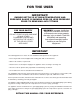
FOR THE USER IMPORTANT! ENSURE KETTLE IS AT ROOM TEMPERATURE AND PRESSURE GAUGE IS SHOWING ZERO OR LESS PRESSURE PRIOR TO REMOVING ANY FITTINGS. FOR YOUR SAFETY DO NOT STORE OR USE GASOLINE OR ANY OTHER FLAMMABLE LIQUIDS AND VAPOURS IN THE VICINITY OF THIS OR ANY OTHER APPLIANCE. WARNING: Improper installation, adjustment, alteration, service or maintenance can cause property damage, injury or death. Read the installation and operating instructions thoroughly before installing or servicing this equipment.
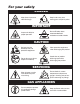
For your safety DANGER Keep clear of pressure relief discharge. Keep hands away from moving parts and pinch points. IMPORTANT Do not fill kettle above recommended level marked on outside of kettle. Inspect unit daily for proper operation. CAUTION Surfaces may be extremely hot! Use protective equipment. Wear protective equipment when discharging hot product. Do not lean on or place objects on kettle lip. Stand clear of product discharge path when discharging hot product.
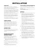
INSTALLATION GENERAL CLEARANCE REQUIREMENTS Installation of the kettle must be accomplished by qualified installation personnel working to all applicable local and national codes. Improper installation of product could cause injury or damage. This unit must be installed in accordance with the clearances shown on the rating label which is adhered to the unit. This equipment is built to comply with applicable standards for manufacturers. Included among those approval agencies are: UL, A.G.A., NSF, ASME/N.
GAS WATER It is recommended that a sediment trap (drip leg) be installed in the gas supply line. If the gas pressure exceeds 14” water column, a pressure regulator must be installed, to provide a maximum of 14” water column gas pressure to the gas control valve. The sealed jacket of the gas-fired kettle is precharged with the correct amount of a water-based formula, and therefore, no water connection is required to the kettle jacket.
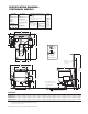
SPECIFICATION DRAWING STATIONARY MODELS ELECTRICAL SUPPLY GAS SUPPLY (PIPING 3/4" NPT) VOLTS: 208/240 TYPE: NAT or LP PHASE: 3 BTU PER CU. FT.: AMPS: 15 1000 (NAT), 2500 (LP) FREQ: 60 HZ APPROVALS AGA CGA NSF SUPPLY PRESSURE: A AIR SUPPLY (PIPING 1/2" NPT) APPROX. SHIPPING WEIGHTS PRESSURE: 90 - 100 PSI (only required for optional 3" dia. piston draw-off valve) H C HOT & COLD WATER 4" to 14" W.C. 1/2" NPT CONNECTION BTU RATINGS: 40-60 PSI PRESSURE 190,000 per hour 60 GAL 1010 LBS.
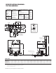
SPECIFICATION DRAWING TILTING MODELS VOLTS: 208/240 TYPE: NAT or LP PHASE: 3 BTU PER CU. FT.: AMPS: 15 1000 (NAT), 2500 (LP) FREQ: 60 HZ CGA NSF APPROX. SHIPPING WEIGHTS PRESSURE: 90 - 100 PSI (only required for optional 3" dia. piston draw-off valve) H C HOT & COLD WATER SUPPLY PRESSURE: APPROVALS AGA A AIR SUPPLY (PIPING 1/2" NPT) GAS SUPPLY (PIPING 3/4" NPT) ELECTRICAL SUPPLY 4" to 14" W.C.
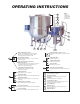
OPERATING INSTRUCTIONS A B C NOTE: Location of switches may vary dependant on customers specific options D E 7 5 6 1 2 4 3 Red Low Water Indicator Light When lit, in the upright position, indicates kettle gas burner has cut out and unit requires more water. Occasional pulsing of this light is normal. A Fill Interrupt Switch Interrupts water fill cycle Green Heat Indicator Light When lit, indicates gas burner is on; cycles on-off with solid state controls.
General WARNING: Do not attempt to operate this appliance during a power failure. Keep appliance and area free and clear of combustibles. Automatic Heating 1. Switch "CONTROLLER" to "ACTIVE". 2. Turn temperature control knob to "10". 3. Continually push function key " displayed. 4. Push and hold key " temperature is set. 5. To Start: push function key Before turning kettle on, ensure that following conditions exist: • If you are cooking an egg or milk product, do not pre-heat kettle.
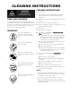
CLEANING INSTRUCTIONS CLEANING INSTRUCTIONS CAUTION SURFACES MAY BE EXTREMELY HOT! CARE AND CLEANING Cooking equipment must be cleaned regularly to maintain its fast, efficient cooking performance and to ensure its continued safe, reliable operation. The best time to clean is shortly after each use (allow unit to cool to a safe temperature). WARNINGS ➩ 2. Remove drain screen (if applicable). Thoroughly wash and rinse the screen either in a sink or a dishwasher. 3.
STAINLESS STEEL EQUIPMENT CARE AND CLEANING (Suppied courtesy of Nafem. For more information visit their web site at www.nafem.org) to reduce deposits. There are certain filters that can be installed to remove distasteful and corrosive elements. To insure proper water treatment, call a treatment specialist. Contrary to popular belief, stainless steels ARE susceptible to rusting. Corrosion on metals is everywhere. It is recognized quickly on iron and steel as unsightly yellow/orange rust.
PRODUCT VALVE SCRAPER BLADES Daily - clean product valve as follows: To remove and clean scraper blades: Scraper blade KETTLE KETTLE OUTLET Back stop Pin A Pin B CLAMP Spring Tool Fig. 1 0-RING VALVE TEE 0-RING Fig. 2 Fig. 3 To Remove Scraper Blade 1. Insert tool that is provided as shown in Fig. 2. 2. Pull up on spring arm until arm clears groove in Pin B. 3. Spring is now disengaged, gently release spring to remove scraper blade. To Install Scraper Blade 1.
AGITATOR QUAD RING To remove and clean agitator (two-person To clean agitator quad ring: job): Quad ring Seal retainer plate Agitator shaft Pin Retaining knobs Coupling Cleaning Quad Ring Removing Agitator 1. Remove retaining knobs. 2. Slide shaft seal retainer plate and quad ring away from kettle body. 3. Clean quad ring, shaft, and seal retainer plate with clean cloth. 1. Remove scraper blades. 2. Rotate agitator until pull pin is on top side. 3. Turn power OFF. 4. Pull pin out. 4.
SERVICE PARTS SCRAPER BLADES ITEM NO. PART NO. DESCRIPTION QTY. 1. KE54602 SCRAPER BLADE . . . . . . . . . . . . . . .7 2. KE54608 SPRING . . . . . . . . . . . . . . . . . . . . . . .7 3. KE01976 SPRING REMOVAL TOOL . . . . . . . . 1 1 3 2 AGITATOR SEAL ASSEMBLY 1 ITEM NO. PART NO. DESCRIPTION 1. KE01911 RETAINING KNOBS . . . . . 3 2. KE54592 SEAL RETAINER PLATE . . 1 3. FA05002-8 "O" RING . . . . . . . . . . . . . . 1 4. KE54594 PIN . . . . . . . . . . . . . . . . . . 1 5.
PRESSURE RELIEF ASSEMBLY 4 3 1 5 2 ITEM NO. PART NO. DESCRIPTION 1. FA05049 MALE CONNECTOR, 1/2" PIPE - 1/4" TUBE . . . . . . . . . . . . . . . . . . . . . . . . . . . .1 2. FI00151 STREET ELBOW, 1/2" . . . . . . . . . . . . . . . . . . . . . . . . . . . . . . . . . . . . . . . . . . . . .2 3. FI00178 TEE, 1/2" FPT, BRASS . . . . . . . . . . . . . . . . . . . . . . . . . . . . . . . . . . . . . . . . . . . . .1 4. KE54941-5 SAFETY VALVE, 50 PSI, 1/2" (NORTH AMERICA) . . . . . . . . . . .
HINGE ASSEMBLY 9 4 7 11 8 6 10 1 9 5 12 ITEM NO. PART NO. DESCRIPTION 13 2 3 QTY. Hinge Assembly 1. - 11 KE50597-1 25 - 40 Gallon, 20 Gallon Full Jacketed . . . . . . . . . . . . . . . . . . . . . . . . . . . . . . .1 KE50597-2 60 - 80 Gallon, 30 - 40 Gallon Full Jacketed . . . . . . . . . . . . . . . . . . . . . . . . . . .1 KE50597-3 100 - 150 Gallon, 60 - 100 Gallon Full Jacketed . . . . . . . . . . . . . . . . . . . . . . . .1 KE50597-4 KDM-60, KDM-60-T, Cook Tank . . . . . . . . . .
WATER METER ASSEMBLY 12 9 10 4 2 8 4 3 2 1 6 4 7 3 2 1 ITEM ON. PART NO. DESCRIPTION QTY. 1. FI00096 3/4 BRASS UNION . . . . . . . . . . . . . . . . . . . . . . . . . . . . . . . . . . . . . . . . . . . . . . .3 2. F100629-2 3/4 NPT X 2 112 BRASS NIPPLE . . . . . . . . . . . . . . . . . . . . . . . . . . . . . . . . . . . .3 3. FI00063 3/4 NPT BRASS ELBOW . . . . . . . . . . . . . . . . . . . . . . . . . . . . . . . . . . . . . . . . . . .4 4. F100629-36 3/4 NPT CLOSE BRASS NIPPLE .
FLUSH PISTON VALVE ITEM NO. (USED PRIOR TO 2003) PART NO. DESCRIPTION QTY. T40430 Valve Assembly (includes parts 1 - 16) . . . . . . . . . . . . . . . . . . . . . . . . .1 1. FA05000 "O" Ring, Cylinder Head . . . . . . . . . . . . . . . . . . . . . . . . . . . . . . . . . . . . .1 2. KE52345 Piston Shaft . . . . . . . . . . . . . . . . . . . . . . . . . . . . . . . . . . . . . . . . . . . . . . .1 3. KE52346 Air seal . . . . . . . . . . . . . . . . . . . . . . . . . . . . . . . . . . . . . .
FLUSH PISTON VALVE & TEMPERATURE SENSOR ASSEMBLIES (USED AFTER TO 2003) 12 13 4 15 14 16 12 AIR VALVE ASSEMBLY FPVA-3 1 5 2 6 3 7 8 9 10 TEMPERATURE SENSOR 8 11 ITEM ON. PART NO. DESCRIPTION QTY. 1. KE55210 WELD RING, KETTLE BOTTOM OUTLET . . . . . . . . . . . . . . . . . . . . . . . . . . . . . 1 2. FI05144-3 SANI CLAMP, 3” . . . . . . . . . . . . . . . . . . . . . . . . . . . . . . . . . . . . . . . . . . . . . . . . . 2 3. KE52154-4 GASKET, SANI CLAMP, 3” . . . . . . . . . . . . .
GEARMOTOR - ELECTRICAL ASSEMBLY 8 1 7 2 3 4 5 6 ITEM NO. PART NO. DESCRIPTION QTY. 1. KE53838-2 TRANSFORMER, 200-240V/440-480V . . . . . . . . . . . . . . . . . . . . . . . . . . . . . . . .1 2. KE50750-2 CONTACTOR . . . . . . . . . . . . . . . . . . . . . . . . . . . . . . . . . . . . . . . . . . . . . . . . . . . .1 3. KE51139-1 FUSE HOLDER . . . . . . . . . . . . . . . . . . . . . . . . . . . . . . . . . . . . . . . . . . . . . . . . . .3 4. KE52936-18 15A FUSE, KLKR . . . . . . . . .
KETTLE - ELECTRICAL COMPONENTS ITEM ON. PART NO. DESCRIPTION QTY. 1. KE53838-19 TRANSFORMER, 120-16V. . . . . . . . . . . . . . . . . . . . . . . . . . . . . . . . . . . . . . . . . .1 KE53444 TRANSFORMER BRACKET . . . . . . . . . . . . . . . . . . . . . . . . . . . . . . . . . . . . . . . . .1 2. KE54833-3 BUSHING . . . . . . . . . . . . . . . . . . . . . . . . . . . . . . . . . . . . . . . . . . . . . . . . . . . . . .1 3. KE02372 IGNITION MODULE, PRIOR TO SEPT. 2004 . . . . . . . . . . . .
KETTLE - GAS COMPONENTS 14 25 5 6 7 8 9 21 15 16 4 17 19 11 26 3 10 26 13 18 1 12 20 26 22 2 24 23
ITEM ON. PART NO. DESCRIPTION QTY. 1. KE53617 SIGHT GLASS . . . . . . . . . . . . . . . . . . . . . . . . . . . . . . . . . . . . . . . . . . . . . . . . . . .1 2. KE53437 IGNITOR . . . . . . . . . . . . . . . . . . . . . . . . . . . . . . . . . . . . . . . . . . . . . . . . . . . . . . .1 3. KE50556-2 WATER LEVEL PROBE . . . . . . . . . . . . . . . . . . . . . . . . . . . . . . . . . . . . . . . . . . . .1 4. KE00515 THERMISTOR . . . . . . . . . . . . . . . . . . . . . . . . . . . . . . . .
CONTROL BOX - ELECTRICAL For front panel control switches see SIDE BOX - TILT MECHANISM & SWITCHES. CONTROL BOX - WATER METER & CHART RECORDER.
ITEM ON. PART NO. DESCRIPTION 1.
CONTROL BOX WATER METER & CHART RECORDER WATER METER START OFF ON EMPTY START CONTINUE RESET EMPTY EMPTY EMPTY EMPTY EMPTY EMPTY BYPASS ACTIVE EMPTY EMPTY EMPTY EMPTY ON EMPTY INTERRUPT OFF EMPTY MAIN POWER 8 2 3 4 5 INDEX 6 Capacitor * Contactor Cartridges 7 5 1 INCLUDED WITH ALL SWITCHES. PART NO. KE52074 * NOTES: KE603208-9 KE603208-8 For units built prior to December 2006, the complete switch assembly must be ordered. ITEM NO. PART NO. DESCRIPTION QTY. 1.
SIDE BOX PNEUMATICS 14 9 13 21 22 9 9 19 16 8 17 5 15 18 2 (NOT SHOWN) 20 RTV ALL AROUND 1 11 12 7 6 4 3 ITEM NO. PART NO. DESCRIPTION QTY. 1. FA05166 QUICK CONNECT . . . . . . . . . . . . . . . . . . . . . . . . . . . . . . . . . . . . . . . . . . . . . . . .1 2. KE54280 SLIDE VALVE . . . . . . . . . . . . . . . . . . . . . . . . . . . . . . . . . . . . . . . . . . . . . . . . . . . .I 3. FA30512 SPACER WASHER . . . . . . . . . . . . . . . . . . . . . . . . . . . . . . . .
22 23 SIDE BOX TILT MECHANISM & SWITCHES 24 21 18 18 48 14 16 15 17 18 20 18 17 19 19 42 45 46 47 29 44 25 26 27 28 43 49 50 51 11 10 9 8 4 3 30 5 52 13 6 53 7 12 31 32 54 55 56 2 40 41 GAS CONNECTION 36 37 38 39 1 35 33 34 SEE PNEUMATIC COMPONENTS DRAWING ITEM NO. PART NO. DESCRIPTION 1. KE50579-1 FA00012 KE50580 KE603208-4 KE51730 KE54531 KE54530 KE54529 KE54532 KE01889 CIRCUIT BREAKER . . . . . . . . . . . . . . . . . . . . . . . . . . . . . . . . . . . . . . .
9. 10. 11. 12. 13. 14. 15. 16. 17. 18. 19. 20. 21. 22. 23. 24. 25. 26. 27. 28. 29. 30. 31. 32. 33. 34. 35. 36. 37. 38. 39. 40. 41. 42. 43. 44. 45. 46. 47. 48. 49. 50. 51. 52. 53. 54.* 55. * 56.
MAINTENANCE INSPECTION AND MAINTENANCE CHECKLIST Cleveland Range equipment requires little preventative maintenance. We do however provide the following chart as a guide line for inspection and maintenance to keep your unit functioning at 100%. MONTHLY INSPECTION Inspect all switches for damage. Replace rubber boots or switches as required. Check that the automatic dump valve works fully and smoothly and no air leaks are evident.
OPERATING SEQUENCE - HEATING STEP ACTION RESULT 1 1. Close main circuit breaker. 120 volts is supplied by primary contactor to kettle On/Off switch and tilt relay contacts. Power supplied to tilt assembly. 2. On/Off switch on kettle switched to ON. 120/16 volt transformer supplies power to control boxes. 3. Control box. A/ Requires grounded probe to function (pin #5). 4. 12 VDC relay contacts close. RESULT 2 Amber LED is illuminated. (Used prior to July 2004) B/ More that 6 volts at pin #2.
KETTLE SAFETY INSPECTION CHECKLIST Regular inspection and maintenance of units is essential to obtain trouble free and safe operation of equipment. Inspections must include testing of the pressure relief valve and checks of the operating system to insure that it has not been altered. No safety features designed into the equipment should ever be tampered with. Tampering with or bypassing controls is a very dangerous practice and unfortunately we have seen several cases of this.
SAFETY THERMOSTAT: Incorrect Installations 1 ✔ Probe fully inserted in tube Wiring is properly connected 2 ✘ ✘ Probe removed partially Probe removed completely 3 ✘ Thermostat electrically bypassed 1 Safety thermostat probe is not completely inserted into tubing. 2 Safety thermostat probe is removed from tubing. 3 Safety thermostat electrical connection is bypassed.
AIR FILTER REPLACEMENT PROCEDURE 1 Disconnect air supply and bleed system. 2. Remove cover on console (see SIDE BOX PNEUMATICS). 3. Check for filter location. 4. Push lever down and rotate bowl/ guard assembly 1/8 turn. Deflector Filter Element Baffle Lever Bowl/Guard Assembly 5. Push down on bowl/guard assembly and remove. NEW SCRAPER BLADE INSTALLATION PROCEDURE Trim corners or center to fit Scraper blade Back stop Move to adjust Spring Fig. 1 Move to adjust Fig. 2 Fig. 3 6.
PRODUCT VALVE OIL FILLING PROCEDURE Replacing O-Rings 1. Disconnect air supply and bleed system. 2. Remove cover on console. 3. Check for oiler location. 4. Inspect oil level in bowl. CLAMP 5. Remove filler cap. 0-RING 6. VALVE TEE Add mineral oil as required. 7. Replace filler cap and console cover. KETTLE KETTLE OUTLET Filler Cap Bowl 0-RING CLAMP 0-RING CLOSED POSTITION OPEN POSITION HINGE ADJUSTMENT INSTRUCTIONS AIR HOSE 3/8" Allen wrench AIR CYLINDER AIR HOSE 1.
KETTLE VENTING INSTRUCTIONS 150 0 250 20 A. Water Level Probe. 30 10 300 40 0 50 IR NT A VE VACUUM LEAK TEST PROCEDURE If the kettle will not hold vacuum, test for leaks at: 200 100 50 Pressure Relief Valve 350 60 Valve Ring 400 psi kPa Access Panel B. Pressure Relief Valve/Pressure Gauge and connecting plumbing. C. Boiler Drain Cap. D. Sight Glass.
RESERVOIR FILL PROCEDURES 150 WARNING: IMPROPER REFILLING OF KETTLE JACKET WILL RESULT IN IRREVERSIBLE DAMAGE TO UNIT. 30 10 300 40 0 IR NT A VE 0 250 20 50 1. Ensure kettle is at room temperature and pressure gauge showing zero or less pressure. 200 100 50 60 psi 350 2. Shut off power to the kettle at the fused disconnect switch. 400 kPa The kettle's water level must be maintained at the proper level.
PRESSURE RELIEF VALVE PERIODIC TESTING Pressure Relief Valve Valve Ring Access Panel Most insurance agencies require periodic testing of pressure relief valves used on pressure vessels. This procedure will allow you to safely and quickly test your kettle's pressure relief valve. We recommend this test be performed twice a year. DANGER: PRESSURE RELIEF VALVE WILL EXHAUST HIGH TEMPERATURE STEAM. CONTACT WITH SKIN COULD RESULT IN SERIOUS BURNS. KEEP FACE, HANDS AND BODY CLEAR OF DISCHARGE.
KETTLE JACKET FILLING & DRAINING PROCEDURES Under normal circumstances the kettle does not require the draining of all fluid. If the red “low water” light is on, follow the RESERVOIR FILL PROCEDURES in this manual. If unit must be drained follow the procedures described on the following pages. WARNING: IMPROPER REFILLING OF DANGER: WORKING ON MACHINES WITH POWER COULD RESULT IN SEVERE ELECTRICAL SHOCK. DANGER: PRESSURE RELIEF VALVE WILL EXHAUST HIGH TEMPERATURE STEAM.
HA DRIVE SHAFT REPLACEMENT PROCEDURE Note: Disconnect external power supply and shut off gas to unit prior to servicing. 1. Remove mixer arm leaving flat surface on drive shaft facing upwards. 2. Remove shaft end cap. 3. Remove shaft retaining bolt. 4. Remove shaft retaining ring.
5. 6. 8. Insert new shaft. 9. Push new shaft past retraining ring groove and install retaining ring. Gently hammer out shaft and remove. Clean seal. 10. Tap shaft back to seat up against retaining ring. 7. Grease seal with food grade grease. 11. Complete reassembly by reinstalling bolt and end cap.
FIELD CONVERSION INSTRUCTIONS Natural Gas to Propane Gas Power Burner Gas Kettles KGL-40, KGL-40-T, MKGL-40-T, KGL-60 to 100, KGL-60-T to 80-T, KGL-40-TSH, KGL-40-F to 60-F, KGL-40-SH to 60-SH, HA-MKGL-60 to 100, HA-MKGL-60 to 100-T BTU's per Hour Gas Type Water Column # of Orifices 140000 140000 NAT LP 3.5 3.5 1 1 “O” RING GAS ORIFICE 190000 190000 NAT LP 3.5 3.5 1 1 SPRING PLUG TOP COVER NOTE: Use thread sealant compatible with propane gas on all threaded piping connections. 1.
SPARE PARTS LIST The following is a spare parts listing of parts that wear during normal us or are apt to be misplaced during normal operation. These parts should be kept on hand to prevent loss time due to a minor problem.
AC INVERTER PROGRAMMING INSTRUCTIONS The WFC Series AC Inverters come wired for external use and must be installed for use in a side panel control (See WIRING DIAGRAMS). Refer to owners manual for complete instructions and explanations. Manual used for the following was FORM 1094. After installation is complete the inverter must be reprogrammed to Cleveland's modifications of the factory settings. All modifications are achieved in Access Level 2. 1. Turn agitator power on.
43 44 45 46 47 48 51 52 53 54 55 56 57 58 59 61 62 DEC1 ACC2 DEC2 DECTL DCBRK DCVLT VSEL BOOST FKNEE SKBND SK1 SK2 SK3 SK4 MVOLT LTLF LTLR Deceleration Time #1 0.10-600 Acceleration Time #2 0.10-600 Deceleration Time #2 0.10-600 Torq. Limit Response Time 0.10-30 DC Brake Time 0-5 DC Brake voltage 0-15 V/Hz Characteristic Selector 0-5 Torque Boost 0-25 V/Hz Knee Frequency 26-640 Skip Fresq. Hysteresis Band 0.20-20 Skip Frequency #1 0.00-400 Skip Frequency #2 0.00-400 Skip Frequency #3 0.
WIRING DIAGRAM - DUAL REMOTE 43
WIRING DIAGRAM SINGLE REMOTE