Operators Manual Installation, Operation & Service Electric Floor Model Kettles For units built after August 1999 MODELS: KEL-25, KEL-30, KEL-40, KEL-40-SH, KEL-60, KEL-80, KEL-100 KEL-25-T, KEL-40-T, KEL-60-T, KEL-80-T, KEL-100-T KEL-40-SH, KEL-40-TSH, KEL-60-SH, KEL-60-TSH ™ Cleveland Enodis 1333 East 179th St., Cleveland, Ohio, U.S.A. 44110 Phone: (216) 481-4900 Fax: (216) 481-3782 Visit our web site at www.clevelandrange.com SE95036 Rev.
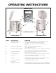
For your safety DANGER Keep clear of pressure relief discharge. Keep hands away from moving parts and pinch points. IMPORTANT Do not fill kettle above recommended level marked on outside of kettle. Inspect unit daily for proper operation. CAUTION Surfaces may be extremely hot! Use protective equipment. Wear protective equipment when discharging hot product. Do not lean on or place objects on kettle lip. Stand clear of product discharge path when discharging hot product.
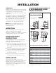
INSTALLATION GENERAL Installation of the kettle must be accomplished by qualified electrical installation personnel working to all applicable local and national codes. Improper installation of product could cause injury or damage. This equipment is built to comply with applicable standards for manufacturers. Included among those approval agencies are: UL, NSF, ASME/Ntl. Bd., CSA, CGA, ETL, and others. Many local codes exist, and it is the responsibility of the owner/installer to comply with these codes.
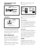
RED YELLOW BLACK 4" MINIMUM, 6" RECOMMENDED RED BLACK SINGLE PHASE BLUE RED THREE PHASE BLACK RECOMMENDED FLOOR FLOOR SLOPE DRAIN 1" IN 4' Note: Maximum voltage for LVD (low voltage directive for Europe) to be 440 volts for CE marked appliances. BLUE RECOMMENDED FLOOR DRAIN DETAIL RED YELLOW BLACK PIPE DRAIN RECOMMENDED MINIMUM VALVE SIZE PLUS 1" L1 L2 L3 L1 L2 The kettle is wired for 3-phase operation at the factory.
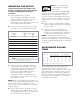
INSTALLATION CHECKS Although the kettle has been thoroughly tested before leaving the factory, the installer is responsible for ensuring the proper operation of kettle once installed. Visual Checks 1. Check Tilting (tilting kettles): A/ Gearbox tilts kettle smoothly and freely. 2. Insure there are: 5. Raise the kettle to the upright position. The Low Water Indicator Light (Red) (3) should go out when the kettle is upright. 6. Turn the ON/OFF Switch/Solid State Temperature Control (1) to "10" (Max.
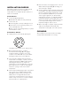
OPERATING INSTRUCTIONS CONTROL PANEL 6 5 7 4 8 3 9 3. 2 1 10 OFF 1. 4. 5. KE95555-2-A 4. 5. 2. 6. 8. 8. CONTROL PANEL TILTING KETTLE STATIONARY KETTLE General Parts Drawing ITEM # DESCRIPTION FUNCTION 1. On-Off Switch/Solid State Temperature Control Turns kettle ON/OFF and allows the operator to adjust the kettle temperature in increments from 1 (Min.) to 10 (Max.). (see Temperature Range Chart in the Operating Instructions section). 2.
OPERATING THE KETTLE DO NOT LEAN ON OR PLACE OBJECTS ON KETTLE LIP. SERIOUS INJURY COULD RESULT IF KETTLE TIPPED OVER, SPILLING HOT CONTENTS. 1. Before turning kettle on, read the Vacuum/Pressure Gauge (4). The gauges needle should be in the green zone. Once heated, the kettle's normal maximum operating pressure is approximately 10-12 psi, while cooking a water base product. 2. Ensure that the electrical service to the kettle is turned on at the fused disconnect switch.
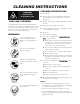
CLEANING INSTRUCTIONS CAUTION SURFACES MAY BE EXTREMELY HOT! CARE AND CLEANING Cooking equipment must be cleaned regularly to maintain its fast, efficient cooking performance and to ensure its continued safe, reliable operation. The best time to clean is shortly after each use (allow unit to cool to a safe temperature). CLEANING INSTRUCTIONS 1. Turn unit off. 2. Remove drain screen (if applicable). Thoroughly wash and rinse the screen either in a sink or a dishwasher. 3.
STAINLESS STEEL EQUIPMENT CARE AND CLEANING (Suppied courtesy of Nafem. For more information visit their web site at www.nafem.org) Contrary to popular belief, stainless steels ARE susceptible to rusting. 4. Treat your water. Though this is not always practical, softening hard water can do much to reduce deposits. There are certain filters that can be installed to remove distasteful and corrosive elements. To insure proper water treatment, call a treatment specialist. Corrosion on metals is everywhere.
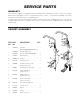
SERVICE PARTS WARRANTY Our Company supports a worldwide network of Maintenance and Repair Centers. Contact your nearest Maintenance and Repair Centre for replacement parts, service, or information regarding the proper maintenance and repair of your cooking equipment In order to preserve the various agency safety certification (UL, NSF, ASME/Ntl. Bd., etc.), only factorysupplied replacement parts should be used. The use of other than factory supplied replacement parts will void warranty.
HINGE ASSEMBLY 9 4 7 11 8 6 10 1 9 5 12 ITEM NO. PART NO. DESCRIPTION 13 2 3 QTY. Hinge Assembly 1. - 11 KE50597-1 25 - 40 Gallon, 20 Gallon Full Jacketed . . . . . . . . . . . . . . . . . . . . . . . . . . . . . . .1 KE50597-2 60 - 80 Gallon, 30 - 40 Gallon Full Jacketed . . . . . . . . . . . . . . . . . . . . . . . . . . .1 KE50597-3 100 - 150 Gallon, 60 - 100 Gallon Full Jacketed . . . . . . . . . . . . . . . . . . . . . . . .1 KE50597-4 KDM-60, KDM-60-T, Cook Tank . . . . . . . . . .
KETTLE BOTTOM & SIDE 11 2 1 3 29 4 28 6 5 31 10 Element Terminals 30 20 18 27 21 22 9 25 26 8 7 24 23 7 19 12 14 16 15 17 ITEM NO. PART NO. DESCRIPTION 1. 2. KE50556-1 KE54941-5 KE54941-31 KE51226 KE51225 KE00458 KE50753-7 KE54761 KE50377 SK50055-1 KE50376 SK50054-1 SK50054-2 KE53838-11 KE53838-12 KE53838-13 Probe, Water Level . . . . . . . . . . . . . . . . . . . . . . . . . . . . . . . . . . . . . . . . . . . . . . .1 Safety Valve, 50 PSI, 1/2" (North America) . . . . . . . . . . .
11. 12. 14. 15. 16. 17. 18. 19. 20. 21. 22. 23. 24. 25. 26. 27. KE000714-4 KE50429-5 SE003013-1 SE003013-2 SE003013-3 SE00115 KE51005 KE50569-1 KE55069-5 KE50515 KE50750-3 KE50750-4 KE50750-5 KE51139-1 KE52936-1 KE54833-3 KE54833-4 KE50473 KE53838-21 KE00688 KE50392 Pressure Gauge, for units built prior to February 2005 . . . . . . . . . . . . . . . . . . .1 Pressure Gauge, for units built after January 2005 . . . . . . . . . . . . . . . . . . . . . .1 L.E.D., Red, Replacement Kit.
CONTROL CONSOLE COMPONENTS - HAND TILT 45 44 43
CONTROL CONSOLE COMPONENTS - HAND TILT ITEM NO. PART NO. DESCRIPTION 1. FA11134 Screw, 10-24 x 3/8" SS . . . . . . . . . . . . . . . . . . . . . . . . . . . . . . . . . . . . . . . . . . . .2 2. KE50325 Gear Box Lid . . . . . . . . . . . . . . . . . . . . . . . . . . . . . . . . . . . . . . . . . . . . . . . . . . . .1 3. FA95008 Locknut, 3/4-16 . . . . . . . . . . . . . . . . . . . . . . . . . . . . . . . . . . . . . . . . . . . . . . . . . .2 4. FA30088 Washer, 1 1/2" 0.D. x 13/16" I.D. x .
CONTROL CONSOLE COMPONENTS - POWER TILT 40 45 44 43 41 42
CONTROL CONSOLE COMPONENTS - POWER TILT ITEM NO. PART NO. DESCRIPTION 1. 2. 3. 4. KE503252 FA11134 KE52832-1 KE53838-8 KE53838-9 KE50583 KE50582 KE50377 SK50055 KE50376 SK50054 FA95008 FA30088 SE00036 FA95005 Gear Box Lid . . . . . . . . . . . . . . . . . . . . . . . . . . . . . . . . . . . . . . . . . . . . . . . . . . . .1 Screw, 10-24 x 3/8" S.S. . . . . . . . . . . . . . . . . . . . . . . . . . . . . . . . . . . . . . . . . . . .1 Motor . . . . . . . . . . . . . . . . . . . . . . . . . . . . . . .
For tilting units with covers TRUNNION ASSEMBLY 1 ITEM PART NO. NO. DESCRIPTION 1. TRUNNION BEARING ASSEMBLY . . . . . .1 (INCLUDES PART # 3 & 6) 2. KE00354 KE00351 QTY. 6 TRUNNION BEARING ASSEMBLY . . . . . .1 (INCLUDES PART # 3 & 6) 3 3. KE51711 ROLLER BEARING . . . . . . . . . . . . . . . . . 2 4 4. KE51571-1 SPHERICAL WASHER . . . . . . . . . . . . . . . .1 5 5. FA95081-3 BOLT, 5/16-18 X 1/2" . . . . . . . . . . . . . . . . .1 6. KE51886 GREASE NIPPLE . . . . . . . . . . . . .
SPARE PARTS LIST ITEM ON. DESCRIPTION QTY. DOMESTIC QTY. OVERSEAS 1 1 Refer to Kettle Bottom & Side for parts drawing KE00458 Solid State Control Box KE50753-7 Relay, 12 VDC KE50750-5 Contactor, 208/240V, 60 Amp.
MAINTENANCE ALL SERVICE MUST BE PERFORMED BY A QUALIFIED SERVICE TECHNICIAN. IMPORTANT! ENSURE KETTLE IS AT ROOM TEMPERATURE AND PRESSURE GAUGE IS SHOWING ZERO OR LESS PRESSURE PRIOR TO REMOVING ANY FITTINGS. Cleveland Range equipment requires little preventative maintenance. We do however provide the following chart as a guideline for inspection and maintenance to keep your unit functioning at 100%.
CALIBRATING PROCEDURE 1. Insure the unit has a vacuum before you begin calibrating procedures. If unit requires venting refer to Kettle Venting Instructions. 2. Set On-Off Switch/Temperature Control to "10" (Max.). 3. Allow the unit to cycle twice. 4. Check temperature of the inner kettle surface with a digital surface thermometer. 5. Temperature should be between 260° F and 265° F. 6. Using a screw driver adjust temperature by turning the potentiometer on the black box. Turn very little.
RESERVOIR FILL PROCEDURES 3. Pull Pressure Relief Valve (A) open to insure vessel is not pressurized. The kettle's water level must be maintained at the proper level to submerge the heater elements. Under normal operating conditions, the sealed water reservoir should never require the addition of water. 5. Replace Pressure Relief Valve (A) with Street Elbow (B).
VACUUM LEAK TEST PROCEDURE WATER LEVEL PROBE If the kettle will not hold vacuum, test for leaks at: PRESSURE GAUGE A. Water Level Probe (Remove bottom cover). B. Pressure Relief Valve. C. Pressure Gauge. LEAK TEST PROCEDURE: 1. Heat kettle until unit cycles off. 2. Shut off power to the kettle at the fused disconnect switch. PRESSURE RELIEF VALVE 3. Spread Bubble Type Leak Detector over suspected are and watch closely for bubbles. 4. Repair areas as required.
KETTLE JACKET CLEANOUT AND PASSIVATION PROCEDURES The following procedure should be preformed at least once every three years to prevent possible corrosion and ensure the optimum life of the kettle. DANGER: WARNING: WORKING ON MACHINES WITH POWER COULD RESULT IN SEVERE ELECTRICAL SHOCK. IMPROPER REFILLING OF KETTLE JACKET WILL RESULT IN IRREVERSIBLE DAMAGE TO UNIT. DANGER: DANGER: MOLYFILM 315 IS CORROSIVE, AVOID CONTACT WITH SKIN AND EYES. EXTREMELY HOT SURFACES. WORK ONLY ON COLD KETTLE.
DIAGNOSTIC GUIDE This section contains servicing information intended for use by Authorized Service Personnel. NOTE 1: If Fault Isolation Procedure is required, be sure to start at step #1. NOTE 2: On table type kettles the entire control mounting panel may be removed from kettle control housing for easier troubleshooting and parts replacement. A/ Problem: Kettle is not heating at all. (Kettle must be on and temperature control set.) Possible Causes 1. No incoming power. 2. Kettle is tilted. 3.
9. 10. 11. Measure continuity of ON/OFF switch/ temperature control. Is it operating properly? Yes Go to step #10. No Replace defective ON/OFF switch/ temperature control. Unplug control box and measure the resistance across potentiometer. Is it approximately 0 ohms at maximum setting and 50,000 ohms at minimum? Yes Go to step #11. No Replace defective potentiometer (ON/OFF switch/temperature control) Remove edge connector from control box.
5. Remove kettle thermistor and allow to cool. Remove edge connector from control box. Test resistance across edge connector's pins #2 and #7. Is it approximately 100,000 ohms? No Replace defective thermistor 6. Turn the potentiometer on the control box clockwise to increase the maximum operating temperature. Does the kettle now achieve maximum operating pressure of 30-35 psi in an empty kettle? Yes Kettle is operating correctly. No Spray contact cleaner on control terminals and edge connector.
WIRING DIAGRAM 200-240v LIMIT OUTSIDE OF NORTH AMERICA
WIRING DIAGRAM 380-600v LIMIT OUTSIDE OF NORTH AMERICA