Operators Manual Installation, Operation & Service Skillets OPEN BASE & MODULAR GAS SKILLETS MODELS SGL-30-TR SGL-40-TR SGM-30-TR SGM-40-TR BULLET FOOT (FRONT) 078160-1 FLANGED FOOT (BACK) 078161-1 ™ Cleveland Enodis 1333 East 179th St., Cleveland, Ohio, U.S.A. 44110 Phone: (216) 481-4900 Fax: (216) 481-3782 Visit our web site at www.clevelandrange.com SE95033 Rev.
FOR THE USER FOR YOUR SAFETY DO NOT STORE OR USE GASOLINE OR ANY OTHER FLAMMABLE LIQUIDS AND VAPOURS IN THE VICINITY OF THIS OR ANY OTHER APPLIANCE. WARNING: Improper installation, adjustment, alteration, service or maintenance can cause property damage, injury or death. Read the Installation and Operating instructions thoroughly before installing or servicing this equipment. IMPORTANT Post in a prominent location, instructions to be followed in the event the user smells gas.
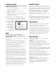
For your safety DANGER Keep hands and utensils away from moving parts and pinch points. ✘ ✘ IMPORTANT Do not lean on or place objects on skillet lip. Inspect unit daily for proper operation. Lift lid before tilting skillet. 1 2 CAUTION Wear protective equipment when discharging hot product. Stand clear of product discharge path when discharging hot product. Surfaces may be extremely hot! Use protective equipment.
INSTALLATION GENERAL INSPECTION Installation of the unit must be accomplished by qualified installation personnel working to all applicable local and national codes. Improper installation of unit could cause injury or damage. Before unpacking visually inspect the unit for evidence of damage during shipping. This equipment is built to comply with applicable standards for manufacturers. Included among those approval agencies are: UL, A.G.A., NSF, ASME/N.Bd., CSA, CGA, ETL, and others.
INSTALLATION VENTILATION KEEP THE APPLIANCE AREA FREE AND CLEAR OF COMBUSTIBLE MATERIALS. A gas skillet must be installed in a location in which the facilities for ventilation permit satisfactory combustion of gas and proper venting. Proper ventilation is imperative for good operation of the appliance.
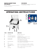
WATER CONNECTIONS (OPTIONAL) CLEANING After installation the unit must be thoroughly cleaned and sanitized prior to cooking. A 3/8" NPT cold water line and a 3/8" NPT hot water line are required for the fill faucet. OPERATING INSTRUCTIONS 3 2 1 7 xttwulql CONTROL PANEL 8 6 ITEM # DESCRIPTION FUNCTION 1. On-Off Switch Main power switch for unit. 2. Power Indicator Light (Red) Indicates power is on. 3.
START UP PROCEDURE 5. Turn power switch to the 'OFF' position when skillet is not in use. This appliance has been factory tested and adjusted under ideal conditions but, rough handling, low gas pressure, altitude or variations in gas characteristics may require fine adjustment. 6. During an electrical power interruption, turn power switch to the 'Off position. This unit cannot be made to operate without electrical power or gas supply.
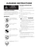
CLEANING INSTRUCTIONS CAUTION SURFACES MAY BE EXTREMELY HOT! CARE AND CLEANING Cooking equipment must be cleaned regularly to maintain its fast, efficient cooking performance and to ensure its continued safe, reliable operation. The best time to clean is shortly after each use (allow unit to cool to a safe temperature). CLEANING INSTRUCTIONS 1. Turn unit off. 2. Remove drain screen (if applicable). Thoroughly wash and rinse the screen either in a sink or a dishwasher. 3.
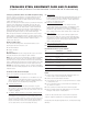
STAINLESS STEEL EQUIPMENT CARE AND CLEANING (Suppied courtesy of Nafem. For more information visit their web site at www.nafem.org) Contrary to popular belief, stainless steels ARE susceptible to rusting. 4. Treat your water. Though this is not always practical, softening hard water can do much to reduce deposits. There are certain filters that can be installed to remove distasteful and corrosive elements. To insure proper water treatment, call a treatment specialist. Corrosion on metals is everywhere.
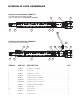
HYDRAULIC JACK ASSEMBLIES Hydraulic Jack Assembly KE000772 For units built prior to February 2005 (replaces old Jack #s SK2381000 & SK00403) 2 5 1 3 6 7 6 Hydraulic Jack Assembly KE000523 11 For units built after February 2005 9 2 8 10 3 1 4 6 10 7 12 4 6 ITEM NO. PART NO. DESCRIPTION QTY. 1 KE600526 HYDRAULIC CYLINDER . . . . . . . . . . . . . . . . . . . . . . . . . . . . . . . . . . . . . . . . . . .1 2 KE600527 PUSH ROD . . . . . . . . . . . . . . . . . . . . . . . . . .
HYDRAULIC JACK ASSEMBLIES HAND TILT For units built prior to October 2001 For complete assemblies see HYDRAULIC JACK ASSEMBLIES. ITEM NO. PART NO. DESCRIPTION QTY. 1 2381000 HYDRAULIC JACK ASSEMBLY . . . . . . . . . . . . . . . . . . . . . . . . . . . . . . . . . . . . .1 (NO LONGER AVAILABLE, USE KE000772) 5 FA95007-7 RETAINING RING . . . . . . . . . . . . . . . . . . . . . . . . . . . . . . . . . . . . . . . . . . . . . . . .4 6 2376503 ACTUATOR PIN (FRONT) . . . . . . . . . . . . . . . . .
ACTUATOR ASSEMBLY POWER TILT (used prior to January, 2000) ITEM NO. PART NO. DESCRIPTION QTY. 1. SK2346100 ACTUATOR . . . . . . . . . . . . . . . . . . . . . . . . . . . . . . . . . . . . . . . . . . . . . . . . . . . . .1 2. SK2337499 ACTUATOR MOUNTING BRACKET ASSY. . . . . . . . . . . . . . . . . . . . . . . . . . . . . .1 3. SK2357600 SLEAVE BEARING . . . . . . . . . . . . . . . . . . . . . . . . . . . . . . . . . . . . . . . . . . . . . . . .1 4. SK2376503 ACUATOR PIN, FRONT . . . . . .
ACTUATOR ASSEMBLY POWER TILT 7 9 (used after January, 2000) 8 9 7 3 10 15 11 14 12 2 1 13 7 7 6 5 4 4 5 ITEM NO. PART NO. DESCRIPTION 1. SK2346100 KE003242 SK2346100-1 SK2346101-1 KE603205 FA11091 FA05002-54 SK2337499 SK00352 SK2357500 SK2376503 FA95007-7 SK2376504 FA30505-3 KE601979 KE601960 KE602198 FA32005 F10 F12 KE002226 ACTUATOR ASSY., COMPLETE WITH ITEM 2 . . . . . . . . . . . . . . . . . . . . . . . . . .1 ACTUATOR ASSY., WITH MANUAL OVERRIDE, COMPLETE WITH ITEMS 2 & 3 . . .
HYDRAULIC TILT ASSEMBLY 24 New (added February 2005) KE600452 (Strainer) FI00351 (Bushing) FI05318-1 (Elbow, hose barb) ITEM NO. PART NO. DESCRIPTION 1 2 3 4 5 6 7 8 9 10 11 12 13 14 15 16 17 19 2379100 2379600 2379501 2379500 2379000 2379001 2378901 2379400 2379301 2382700 2378900 2375699 2250700 2376200 078279-1 FA95079 FI05059 2379200 HYDRAULIC ADAPTOR . . . . . . . . . . . . . . . . . . . . . . . . . . . . . . . . . . . . . . . . . . .2 HYDRAULIC HOSE ASSY . . . . . . . . . . . . . . . . . . . .
CONTROL PANEL 22 21 ITEM NO. PART NO. 1 2474101 2474100 2343500 2343502 2343501 SK2533199 2138700 2360701 2360700 KE95586-1 KE95586-2 KE95586-3 KE95586-4 2356100 2356102 SE00119 2142002 2498399 SK50872-1 SK50872-2 F33 2147403 2147402 2147401 2147400 2352898 2353100 2383200 2357900 KE55069-7 SK00383-1 SK00383-2 SK00383-3 SK00383-4 SK50905-1 SK50905-2 SK50903 2 3 4 5 6 7 8 8A 8B 9 10 11 12 13 14 15 16 17 18 19 20 21 22 DESCRIPTION QTY. POWER SWITCH (240V, USED AFTER FEBRUARY 2001) . . . . . . . .
SHAFT ASSEMBLY 1 4 2 5 6 7 11 8 12 3 13 9 10 DESCRIPTION 14 ITEM NO. PART NO. QTY. 1. SE00119 THERMOSTAT BOARD ASSEMBLY (INCLUDES 2 - 14) 1 2. SK2142002 TEMPERATURE SENSOR BOARD 1 3. SK2159300 INSULATOR, THERMOSTAT 1 4. SK2498399 POTENTIOMETER SHAFT ASSEMBLY (INCLUDES 5-10) 1 5. SK2167200 RETAINING RING, SP-NR #R1000-25 1 6. SK2167100 WASHER, BOWED/SPRING 1 7. SK2167300 PANEL BEARING 1 8. SK2382800 RETAINING RING CLIP 1 9. SK2167000 TENSION PIN 1 10.
ELECTRICAL BOX Component Box Cover 2343900 Component box assembly 2343699 Igniton cable SE50450 ITEM NO. PART NO. DESCRIPTION 1 KE53838-32 KE53838-31 KE53838-30 KE53838-25 KE53838-18 1427305 2282100 1426600 KE50581 2320702 KE52936-7 KE52936-10 KE52936-13 KE52936-11 KE52936-9 KE52936-8 2147403 2147400 2147401 2361500 2329100 SK50872-1 SK50872-2 2361700 2348100 2383300 2343699 TRANSFORMER - POWER TILT - 110-120V/60 . . . . . . . . . . . . . . . . . . . . . . . . .
PLATE ASSEMBLY (used prior to January, 2000) ITEM NO. PART NO. DESCRIPTION 1 2 3 4 5 6 7 KE55069-7 2353900 2354099 F95 2345100 2344900 2345000 HI-LIMIT BULB CLAMP BULB SHIELD ASSY NUT RTD SENSOR SHIELD LINER SHIELD QTY. 1 1 1 1 1 1 1 PAN HINGE 13 14 For units with TD Valve ITEM NO. PART NO. DESCRIPTION QTY. 1 2 3 4 5 6 7 8 9 11 13 14 FA21053 FA30505-3 078248-1 G02925-2 FA15015 FA10245 FA21004 2354199 FA11224 FA21024 FA15019-2 SK50813 LOCK NUT 1/2-13 S.S. . . . . . . . . . . . . . . . . . . .
SPRING ASSEMBLY ITEM NO. PART NO. DESCRIPTION QTY. 1 2452300 SPRING 2 2381700 TURNBUCKLE BODY . . . . . . . . . . . . . . . . . . . . . . . . . . . . . . . . . . . . . . . . . . . . . . . . . .2 3 2374900 CONNECTING ROD R/H THREAD . . . . . . . . . . . . . . . . . . . . . . . . . . . . . . . . . . . . . . . .2 2374901 CONNECTING ROD L/H THREAD . . . . . . . . . . . . . . . . . . . . . . . . . . . . . . . . . . . . . . . .2 4 2529499 BELL CRANK ASSY . . . . . . . . . . . . . . . . . . . . .
BURNER BOX ASSEMBLY ITEM NO. PART NO. DESCRIPTION 1 2 2359300 2360101 2360100 2342499 2342399 071497-2-9 2342602 2342600 2342601 2445200 2445201 2445300 2445400 2347800 2347900 2342200 2342100 2373900 SK50890 SK50891 SK50892 SK50893 BACK TOP MOUNTING BRACKET . . . . . . . . . . . . . . . . . . . . . . . . . . . . . . . . . . .2 REAR COMBUSTION SEAL - 40 GAL. . . . . . . . . . . . . . . . . . . . . . . . . . . . . . . . .1 REAR COMBUSTION SEAL - 30 GAL. . . . . . . . . . . . . . . . . . . . . . . . . .
MANIFOLD ASSEMBLY ITEM NO. PART NO. DESCRIPTION 1 2373100 BURNER (NAT. GAS) . . . . . . . . . . . . . . . . . . . . . . . . . . .7 for 30 gal., 10 for 40 gal. KE02410 BURNER (LP GAS) . . . . . . . . . . . . . . . . . . . . . . . . . . . .7 for 30 gal., 10 for 40 gal. KE55277-1 ORIFICE, (NAT. GAS), 2000 FT . . . . . . . . . . . . . . . . . . .7 for 30 gal., 10 for 40 gal. KE55277-5 ORIFICE, (LP), 2000 FT. . . . . . . . . . . . . . . . . . . . . . . . .7 for 30 gal., 10 for 40 gal.
MAINTENANCE NOTE: ANY MAINTENANCE OR SERVICE INVOLVING DISSASSEMBLY OF COMPONENTS SHOULD BE MADE BY A QUALIFIED SERVICE TECHNICIAN. ENSURE GAS, ELECTRICAL AND WATER SUPPLY (IF APPLICABLE) TO THE APPLIANCE ARE SHUT OFF You have purchased the finest commercial cooking equipment available anywhere. Like any other fine, precision built piece of equipment it should be given regular care and maintenance.