Operators Manual Installation, Operation & Service Electric Table Top Mixers MODELS: MKET-12-T, MKET-20-T ™ Cleveland Enodis 1333 East 179th St., Cleveland, Ohio, U.S.A. 44110 Phone: (216) 481-4900 Fax: (216) 481-3782 Visit our web site at www.clevelandrange.com SE95015 Rev.
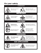
For your safety DANGER Keep clear of pressure relief discharge. Keep hands away from moving parts and pinch points. IMPORTANT Do not fill kettle above recommended level marked on outside of kettle. Inspect unit daily for proper operation. CAUTION Surfaces may be extremely hot! Use protective equipment. Wear protective equipment when discharging hot product. Do not lean on or place objects on kettle lip. Stand clear of product discharge path when discharging hot product.
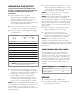
INSTALLATION GENERAL INSTALLATION Installation of the kettle must be accomplished by qualified electrical installation personnel working to all applicable local and national codes. Improper installation of product could cause injury or damage. The first installation step is to refer to the Specification Sheets or Specification Drawings for detailed clearance requirements of the kettle. Next, carefully cut open the shipping carton for easy removal of the kettle.
WIRE CONNECTION RED YELLOW BLACK RED BLACK SINGLE PHASE BLUE RED BLACK THREE PHASE BLUE If unit does not have cord and plug option, remove the screw at the rear of the console cover and remove the cover. A wiring diagram is affixed to the underside of the cover. Feed permanent copper wiring through the cut-out in the rear or bottom of the console, and fasten to the three connection terminal block, which is mounted on the top of the console’s control panel.
OPERATING INSTRUCTIONS 11 15 13 7 12 14 6 5 4 3 2 1 8 9 10 General Parts Drawing ITEM # DESCRIPTION FUNCTION 1. 2. 3. 4. On-Off Toggle Switch Solid State Temperature Control Knob Heat Indicator Light (Green) Low Water Indicator Light (Red) 5. Vacuum/Pressure Gauge 6. Pressure Relief Valve 7. 8. 9. Kettle Tilt Handle Marine Lock Agitator Speed Control Knob 10. 11. 12. 13. 14. 15.
OPERATING THE KETTLE DO NOT LEAN ON OR PLACE OBJECTS ON KETTLE LIP. SERIOUS INJURY COULD RESULT IF KETTLE TIPPED OVER, SPILLING HOT CONTENTS. 1. Before turning kettle on, read the Vacuum/Pressure Gauge (5). The gauges needle should be in the green zone. Once heated, the kettle's normal maximum operating pressure is approximately 10-12 psi, while cooking a water base product. 2. Ensure that the electrical service to the kettle is turned on at the fused disconnect switch. 3.
MARINE LOCK LATCH Your unit is equipped with a marine lock to prevent accidental tilting. The following procedure should be used to tilt the kettle. 1. Grasp the tilt handle. MARINE LOCK TESTING PROCEDURE 2. Hold the latch down to unlock tilting mechanism. 3. Pull the handle to tilt kettle. 4. To lock, return the kettle to its upright position and push handle back. NOTE: Inspect lock daily to ensure it is free moving and does not bind or stick. Clean lock if necessary.
CLEANING INSTRUCTIONS CAUTION SURFACES MAY BE EXTREMELY HOT! CARE AND CLEANING Cooking equipment must be cleaned regularly to maintain its fast, efficient cooking performance and to ensure its continued safe, reliable operation. The best time to clean is shortly after each use (allow unit to cool to a safe temperature). CLEANING INSTRUCTIONS 1. Turn unit off. 2. Remove drain screen (if applicable). Thoroughly wash and rinse the screen either in a sink or a dishwasher. 3.
AGITATOR ASSEMBLY 1. Place the Kettle’s On-Off Toggle Switch (1) to the "OFF' position. 4. Scraper blades can be removed by sliding them up the arm and rotating until free. 5. Clean all parts. 2. Raise Mixer Bridge (11). 3. Push Main Agitator Arm towards Bayonet Mount (15), rotate counterclockwise and then pull out to remove. Repeat process for Secondary Agitator Arm (14). MARINE LOCK Use a small nylon bristle brush to remove food and debris from pivot point.
STAINLESS STEEL EQUIPMENT CARE AND CLEANING (Suppied courtesy of Nafem. For more information visit their web site at www.nafem.org) Contrary to popular belief, stainless steels ARE susceptible to rusting. 4. Treat your water. Though this is not always practical, softening hard water can do much to reduce deposits. There are certain filters that can be installed to remove distasteful and corrosive elements. To insure proper water treatment, call a treatment specialist. Corrosion on metals is everywhere.
SERVICE PARTS WARRANTY Our Company supports a worldwide network of Maintenance and Repair Centers. Contact your nearest Maintenance and Repair Centre for replacement parts, service, or information regarding the proper maintenance and repair of your cooking equipment In order to preserve the various agency safety certification (UL, NSF, ASME/Ntl. Bd., etc.), only factorysupplied replacement parts should be used. The use of other than factory supplied replacement parts will void warranty.
KETTLE BOTTOM 7b 13 2 14 3 4 15 5 1 16 11 8 9 6 12 7a ITEM NO. PART NO. DESCRIPTION 1. 2. 3. 4. 5. 6. 7a. 7b. Fl05025 KE50570 KE50556-1 KE50997 KE51723 F105022 SE00104 Elbow, 1/2" street . . . . . . . . . . . . . . . . . . . . . . . . . . . . . . . . . . . . . . . . . . . . . . . . .1 Filler Vent Valve . . . . . . . . . . . . . . . . . . . . . . . . . . . . . . . . . . . . . . . . . . . . . . . . . .1 Probe, Low Water . . . . . . . . . . . . . . . . . . . . . . . . . . . . . . . . . . . . .
ELECTRICAL PANEL 13 ITEM NO. PART NO. DESCRIPTION 1. KE54761 Terminal Block Mounting Strip 1 2. SK50055-1 Terminal Block 3 3. SK50054-2 Terminal Block End Anchor 1 4. SK50054-1 Terminal Block End Barrier 1 5. KE50753-7 Relay, 12 VAC 1 6. KE50749-2 Contactor, 208-240v 2 7. KE51139-1 Fuse Holder (480v only) 2 8. KE52936-1 Fuse (480v only) 2 9. KE53838-21 Transformer 1 10. KE00458 Kettle Control Box 1 11. KE51225 Edge Connector, 10 Pin 1 5 12.
CONTROL HOUSING
CONTROL HOUSING ITEM NO. PART NO. DESCRIPTION QTY. 1 SK50050 Console Cover . . . . . . . . . . . . . . . . . . . . . . . . . . . . . . . . . . . . . . . . . . . .1 KE54846-1 Gasket, Console Cover . . . . . . . . . . . . . . . . . . . . . . . . . . . . . . . . . . . . .1 2 FA11144 Screw, 10 - 32 x 1/4' SS . . . . . . . . . . . . . . . . . . . . . . . . . . . . . . . . . . . . .1 6 KE50497 Bearing, Trunnion . . . . . . . . . . . . . . . . . . . . . . . . . . . . . . . . . . . . . . . . . .
BRIDGE ASSEMBLY
BRIDGE ASSEMBLY ITEM NO. PART NO. DESCRIPTION 1 KE50342 Bushing, Taper Lock . . . . . . . . . . . . . . . . . . . . . . . . . . . . . . . . . . . . . . . .2 2 KE50284 Pulley, Large . . . . . . . . . . . . . . . . . . . . . . . . . . . . . . . . . . . . . . . . . . . . . .2 3 KE51763 Be It (MKET-10-T) . . . . . . . . . . . . . . . . . . . . . . . . . . . . . . . . . . . . . . . . . .1 KE51808 Belt (MKET-20-T) . . . . . . . . . . . . . . . . . . . . . . . . . . . . . . . . . . . . . . . . . . .
GEAR BOX A NOTE: Insert bolts in opposite holes for taper lock bushing removal.
GEAR BOX ITEM NO. PART NO. DESCRIPTION A KE00107 Complete Assembly, MKET-12-T . . . . . . . . . . . . . . . . . . . . . . . . . . . . . .1 KE00104 Complete Assembly, MKET-20-T . . . . . . . . . . . . . . . . . . . . . . . . . . . . . .1 FA95039 Dowel Pin, 1/4" x 28 (MKET-12-T) . . . . . . . . . . . . . . . . . . . . . . . . . . . . . .2 FA95004 Dowel Pin, 3/8" x 3" (MKET-20-T) . . . . . . . . . . . . . . . . . . . . . . . . . . . . . .2 FA11510 Screw, Socket Head Cap, 5/16-18 UNCx 1-3/4" . . .
MAINTENANCE ALL SERVICE MUST BE PERFORMED BY A QUALIFIED SERVICE TECHNICIAN. Cleveland Range equipment requires little preventative maintenance. We do however provide the following chart as a guideline for inspection and maintenance to keep your unit functioning at 100%. INSPECTION AND MAINTENANCE CHECK LIST The following check should be completed every six months or more frequently if unit is in a high volume facility.
BEARING LUBRICATING PROCEDURE 1. Remove console cover. 2. Loosen two Allen screws on locking ring. 3. Pull locking ring to center of trunnion. 4. Pull kettle two inches away from console and rest on support block. 5. Clean newly exposed sections of trunnion. 6. Grease trunnion between kettle and console. 7. Repack outer needle bearing. 8. Push kettle back in place. 10. Reinstall trunnion and lock collar. 11. Replace console cover.
CALIBRATING PROCEDURE 1. Insure the unit has a vacuum before you begin calibrating procedures. If unit requires venting refer to KETTLE VENTING INSTRUCTIONS. 2. Set On-Off Switch/Temperature Control to "10" (Max.). 3. Allow the unit to cycle twice. 4. Check temperature of the inner kettle surface with a digital surface thermometer. 5. Temperature should be between 260° F and 265° F. 6. Using a screw driver adjust temperature by turning the potentiometer on the black box. Turn very little.
RESERVOIR FILL PROCEDURES 3. Pull Pressure Relief Valve (A) open to insure vessel is not pressurized. The kettle's water level must be maintained at the proper level to submerge the heater elements. Under normal operating conditions, the sealed water reservoir should never require the addition of water. 5. Replace Pressure Relief Valve (A) with Street Elbow (B).
VACUUM LEAK TEST PROCEDURE If the kettle will not hold vacuum, test for leaks at: WATER LEVEL PROBE PRESSURE RELIEF VALVE CHROME VENT NUT A. Water Level Probe B. Pressure Relief Valve C. Chrome Vent Nut and Plug D. Vacuum Pressure Gauge Fittings and Sight Glass. LEAK TEST PROCEDURE: 1. Heat kettle until unit cycles off. 2. Shut off power to the kettle at the fused disconnect switch. 3. Remove bottom cover. PRESSURE GAUGE 4.
KETTLE JACKET CLEANOUT AND PASSIVATION PROCEDURES The following procedure should be preformed at least once every three years to prevent possible corrosion and ensure the optimum life of the kettle. DANGER: WARNING: WORKING ON MACHINES WITH POWER COULD RESULT IN SEVERE ELECTRICAL SHOCK. IMPROPER REFILLING OF KETTLE JACKET WILL RESULT IN IRREVERSIBLE DAMAGE TO UNIT. DANGER: DANGER: MOLYFILM 315 IS CORROSIVE, AVOID CONTACT WITH SKIN AND EYES. EXTREMELY HOT SURFACES. WORK ONLY ON COLD KETTLE.
do wn fo rc lar ity PRESSURE GAUGE "O" RING REPLACEMENT PROCEDURE 1. Switch kettle OFF and disconnect main power at fused disconnect switch. ;; ;; ;; ;; ;; ;; ;; ;; ;;;;;;;;;; ;;;;;;;;;; ;;;;;;;;;; ttle Ke 2. Secure kettle in tilted position. Remove bottom cover. s wn ho sid up e BRACKETS 3. Loosen pressure gauge compression nut.
DIAGNOSTIC GUIDE This section contains servicing information intended for use by Authorized Service Personnel. NOTE 1: If Fault Isolation Procedure is required, be sure to start at step #1. NOTE 2: On table type kettles the entire control mounting panel may be removed from kettle control housing for easier troubleshooting and parts replacement. A/ Problem: Kettle is not heating at all. (Kettle must be on and temperature control set.) Possible Causes 1. No incoming power. 2. Kettle is tilted. 3.
9. 10. 11. Measure continuity of ON/OFF switch. Is it operating properly? Yes Go to step #10. No Replace defective ON/OFF switch. Unplug control box and measure the resistance across potentiometer. Is it approximately 0 ohms at maximum setting and 50,000 ohms at minimum? Yes Go to step #11. No Replace defective potentiometer. Remove edge connector from control box. While kettle is cold or thermistor is removed and allowed to cool, measure the resistance between edge connector’s pins #2 and #7.
5. Remove kettle thermistor and allow to cool. Remove edge connector from control box. Test resistance across edge connector's pins #2 and #7. Is it approximately 100,000 ohms? No Replace defective thermistor 6. Turn the potentiometer on the control box clockwise to increase the maximum operating temperature. Does the kettle now achieve maximum operating pressure of 30-35 psi in an empty kettle? Yes Kettle is operating correctly. No Spray contact cleaner on control terminals and edge connector.
WIRING DIAGRAM