
Specifications


paste into the insulation, the use to coat each heat pipe tip with a thin layer and remove any excess from
the tip. Using this method half a tube can coat 30 tubes.
d) Shake: Heat pipes contain a small amount of copper powder, which aids in heat transfer and provides
freeze protection within the heat pipe itself. To ensure that the powder is at the bottom of the heat pipes,
where is needs to be, before installing the tube and heat pipe, they should inverted (Fat bulb down),
returned upright (Fat bulb at top) and then shaken up and down a few times to ensure the powder has all
returned to the bottom. This should be done at ground level where there is no risk of hitting the tube on
another object.
NOTICE
Donʼt forget to “shake” the tubes with heat pipes inserted as failure to do so may
negatively effect the freeze protection properties.
5.7.2. Heat Pipe and Evacuated Tube Insertion
a) Lubricate Tube: Lubricate the top outer surface of the evacuated tube with a small amount of water. This
facilitates easy insertion past the manifold rubber ring seal. A small pump spray bottle is the best method
for carrying and applying the water.
Note: DO NOT SPRAY WATER INTO THE EVACUATED TUBE
b) Insert Tube: While ensuring the metal spring plate is sitting in the mouth of the evacuated tube, firmly
hold the evacuated tube and guide the heat pipe tip in past the manifold rubber seal and into the heat pipe
port. Ensure the heat pipes are at the TOP DEAD CENTER of the evacuated tube and therefore aligned
correctly with the heat pipe port.
c) Insert Tube - Rotating: Using no more than a 1/8
th
turn left and right twisting action, push the evacuated
tube up into the manifold. The neck of the evacuated tube will push against the spring at the base of the
heat pipe tip, forcing it fully into the port. DO NOT over rotate the tube when inserting otherwise the heat
pipe will be turned out of alignment with the top of the tube, which will prevent proper heat pipe operation.
d) Correct Insertion Depth: The heat pipe and evacuated tube are fully inserted once the black coating of
the evacuated tube has disappeared up into the manifold and no clear glass above the coating is visible.
The bottom of the tube will sit so that the groove on the rubber cap lines up with clip point on the bottom
track.
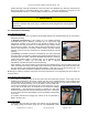
e) Secure Tube: As each tube is inserted (recommended) or, alternatively, once all tubes have been
inserted, secure the tubes to the bottom track using the stainless steel clips as follows:
Step 1. Position the rubber cap so it is aligned with the bottom track and the Apricus logo is at the top.
This ensures that drain holes in the cap are properly positioned. It DOES NOT have to be pushed hard
up on the tube.
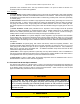
Step 2. Line up the clip with the hook on the bottom track and push
down over the rubber cap. Favoring whichever side is more natural for
you. When it engages you will hear a “click.”
Step 3. Without losing the first hook, center the clip over the top of the
rubber cap and push down the other side until it “clicks” into position.
Step 4. Check to ensure both sides are correctly clipped over the hooks.
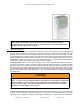
f) Clip Removal: The clip can be removed by using a screwdriver or needle
nosed pliers to pull each side of the clip down and outward. Very little force is
required.
g) Tube Movement: If clipping tubes after all the them have been inserted, it
may be necessary to push an adjacent tube slightly off to the side, while
attaching the clip to allow enough room to operate. There is some flexibility
in the manifold connection and the heat pipe and tube will not be damaged
by this slight sidewards movement. Do not be too aggressive.
Apricus Solar Collector Installation & Operation Manual - USA
Copyright © 2011 – Apricus Inc Doc: A7-05.4.12-PB Page 42 of 129