
Specifications


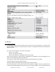


6.3. Sensors
6.3.1. Sensor Information
a) The Apricus controller comes pre-wired for power and control of the Grundfos pump. All sensor wires
must be installed manually. The controller is able to read up to 5 temperature sensors as well as data from
digital flow meters.
The most common positions for the sensors are as follows:
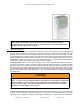
Sensor 1 (T1): Collector
Sensor 2 (T2): Bottom of the tank
Sensor 3 (T3): Between ⅓ and halfway down from top of tank
Correct sensor locations for various system configurations are presented in the system diagrams in the
Apricus OG-300 Schematics and Parts List Manual.
b) The Apricus controller utilizes PT1000 type sensors (thermistors) that have no polarity.
c) Sensors should not be fully immersed in water.
d) Sensors should be coated with silicone thermal paste to aid heat transfer.
e) Protect Sensor Wires: Sensor wires should not be exposed to sunlight and must be protected from
contact with sharp metal edges that could cut the wire or through its insulation. This is especially important
Apricus Solar Collector Installation & Operation Manual - USA
Copyright © 2011 – Apricus Inc Doc: A7-05.4.12-PB Page 45 of 129