
Specifications


when pulling the T1 wire through the roof space. The collector sensor wire must not be run underneath the
insulation against the metal pipe as high temperatures will interfere with accurate readings to the controller
and can damage the wire.
6.3.2. Temperature Sensor Installation - Collector
a) Sensor Well Location: The temperature should be measured at the hottest point in the collector: the
outlet of the collector manifold or the outlet of the last collector manifold in a series. There is a temperature
sensor well next to both plumbing ports on the collector. This allows whichever port is most convenient for
the particular installation to be chosen as the outlet.
b) Sensor Insertion: The solar controller’s temperature sensor should be coated with a thin layer of heat
transfer paste (same as is used on the heat pipe bulbs) and inserted into the sensor well to the full depth.
The fit may be a bit loose.
c) Water Ingress: Use a silicone sealant to prevent water ingress and to help secure the sensor inside the
well.
d) High Temperatures: Ensure that sensors and, in particular, the sensor wire used on the collector are
high temperature rated 395
°
F (200
°
C). Make sure that the wire can also be used in an exterior environment.
e) Sensor Wire:
i) Do not run the wire directly against the metal pipe as the wire may be damaged, instead run outside
the insulation.
ii) Do not run the wire inside conduit with electrical cables (check local electrical code).
iii) Use cable ties (11”cable ties fit nicely around 3/4” pipe with 3/4” wall insulation) to secure at regular
intervals. Avoid loose, drooping wire, keep it close to the insulation.
iv) Some line-sets include a wire beneath the outer wrap. This should be connected to the sensor wire
with good quality, watertight soldered or plug connection. There are weather-resistant connectors
available with a silicone crush pack inside, these are ideal.
v) The wire can be extended up to 60’ (20 m) using appropriately rated 18/2 thermostat wire. For
longer distances, thicker gauge wire may be needed. After installing sensors with long extensions,
check to ensure accurate temperature readings are being provided. The easiest way to do this is to
have a cup of cold water and a cup of hot water along with a hand held digital thermometer; simply
compare the readings from the sensor on the controller to the hand held readings.
vi) Ensure the wire is not able to rub against any surfaces that could cause wear or cut the casing.
Poor sensor readings are often caused by electrical interference with the wire or exposed wiring shorts
etc.
6.3.3. Temperature Sensor Installation - Tank
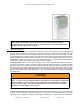
a) Solar Ready Tanks: All tanks recommended for use in Apricus OG-300 systems have a sensor well
located at the bottom of the tank. Refer to tank manufactures installation guide for exact location.
NOTICE
All sensor wiring must be protected from environmental influence which would otherwise
effect their intended operation.
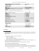
6.4. Electrical & Sensor Connection
a) Diagram below provides details of the power, relay and sensor connections.
Apricus Solar Collector Installation & Operation Manual - USA
Copyright © 2011 – Apricus Inc Doc: A7-05.4.12-PB Page 46 of 129