
Specifications


WARNING
Any electrical work must be performed by a licensed electrician and adhere to local
electrical safety regulations, as required.
Do not connect controller to power supply until all wires are connected and the front case is
closed. Also, make sure the controller does not turn on the pump until it is flooded. Take
care when working near electricity, especially in wet areas.
b) In North America, Apricus controllers are 110 Volts, 60 Hz. They should not be used with higher voltage
power supplies.
c) It is highly recommended that the solar loop (copper or stainless steel) be grounded to avoid lighting
related damage. In areas prone to lightning strikes, the power supply to the controller should also be
suitably protected.
d) The Apricus controllers are supplied with a standard North American plug. No cutting or extension of the
cable is permitted unless completed by a qualified electrician.
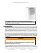
e) The Apricus controller is suitable for INDOOR use only. Also, ensure the operating temperature is within
the acceptable range 32
°
F - 122
°
F and the unit is not exposed to high humidity or condensation.
6.5. Controller Functions
a) Controller Purpose: The primarily purpose of the Apricus controller is to regulate the operation of the
solar circulation pump(s). Many additional functions are also available, including: regulating tank
temperature, providing freeze protection, measuring energy output and more.
b) Basic Operation: In a solar water heating system, maximum efficiency is attained by extracting heat
from the collector as quickly as possible, thus allowing the collector to run at the lowest possible
temperature. The controller achieves this by measuring the temperature at the outlet of the solar collector
and also the bottom of the solar storage tank. This temperature difference is referred to as a delta-t, often
written as ∆t. When the collector is hotter than the bottom of the tank by a set amount, usually between 8°F
and 20°F (5°C and 11°C) the controller will supply power to the pump which circulates water through the
collector. Once the temperature difference drops below a minimum the pump turns off again. This cycle
continues throughout the day. The frequency and duration of pump operation is dependent on solar
radiation levels.
If the variable speed function is activated (recommended), the speed of the pump will be automatically
regulated by the controller to maintain an optimum flow rate and keep the collector between the maximum
and minimum delta-t set levels. This maximizes the system efficiency and also reduces electricity usage.
c) Basic Functions: Basic functions for closed loop and direct flow system are presented in sections 7.11.2
and 8.10.2 respectively. Also, refer to the system schematics in the Apricus OG-300 Systems Manual for
recommended settings for each system configuration.
d) Pump Run Times with ON/OFF Pump Control: The correct delta-t setting (dTMax tank1 & dTMin tank1)
will vary slightly from system to system depending on the flow rate and length of the pipe run. Optimally,
each time the pump operates, the heat in the collector is transferred all the way back to the tank and is not
allowed to sit in the Return Line, where it would otherwise loose heat.
For example: A 16 ft (5 m) pipe run in ½” copper has a fluid content of about 0.24 gallons, plus 0.2 gallons
for an AP-30 collector. With a total of 0.44 gallons, a flow rate of 0.8 gpm would take 20-25 seconds to
transport the hot fluid in the collector back to the tank. A longer pump run time would waste electricity and
promote heat loss from the pipes.
A more common pipe run length of 40 ft (12 m) in ½” copper has a fluid content of 0.48 gallons, plus 0.2
gallons for an AP-30 collector. With a total of 0.68 gallons, a flow rate of 0.5 gpm would take about 60
seconds to transport the fluid in the collector back to the tank.
This basic calculation can help to determine how long the pump should be running for each cycle. See
below for recommended controller settings. The operation of the pump can be tested by feeling the flow
and return lines (or using temperature probes if too hot). The pump should turn off shortly after the heat has
returned back down the return line and the temperature drops to a similar level as the flow line.
Apricus Solar Collector Installation & Operation Manual - USA
Copyright © 2011 – Apricus Inc Doc: A7-05.4.12-PB Page 47 of 129