
Specifications

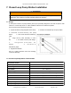


d) Pressure Relief: The pressure relief valve is included as a safety device, designed to open at 75 psi
should the system pressure rise to that level. This may occur if for example the expansion tank is not big
enough or some blockage occurs that prevent normal operation or extreme overheating occurs.
e)Drain Pipe: The pressure relief valve drain pipe fitting is a 3/4” FPT connection. Install and tighten drain
pipe fitting with two wrenches taking special care not to stress the pressure relief valve support pipe.
WARNING
- Pressure relief valve must NOT be blocked.
- A drain pipe must be connected to the relief valve.
- The drain pipe diameter must be no smaller than 3/4” and be able to withstand
temperature of up to 230
°
F (110
°
C).
- Pressure relief piping must meet local codes
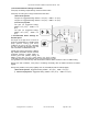
7.6. Controller Connections
a) The Apricus controller comes pre-installed on the left side of the pump station.
b) Remove the controller cover by removing the screw with a small straight blade or star screwdriver. Pull
the cover straight off to expose the electrical (left) and sensor (right) terminal connections.
c) Install system temperature sensors. (See section 6.4)
Step 1. Insert collector sensor (RED high temp wire) into collector sensor well on the solar return side
of the collector. Route the wire along the return pipe to the pump station avoiding direct contact with
the pipe.
NOTICE
Do not install the sensor wires in direct contact with system pipes. Route sensor wires on
the outside of system pipe insulation whenever possible.
Step 2. Insert storage tank sensor (GRAY wire) into storage tank sensor well. Route the wire along the
return pipe to the pump station avoiding direct contact with the pipe.
Step 3. Remove the wire strain relief bar on sensor terminal side of controller.
Step 4. Connect the red collector sensor wire to T1 terminals (red and white wires).
Connect grey storage tank sensor to T2 terminals (brown and white wires).
Step 5. Replace wire strain relief bar.
d) Sensors wires can be fed through the pump station and out the top to run along the collector return pipe
or out the bottom along the tank return pipe (OUTSIDE THE INSULATION).
e) Once all wires are connected to the controller the cover can be replaced.
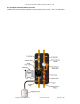
7.7. Pump Operation
a) Fixed Speed Operation: The Apricus Closed Loop Pump station is supplied standard with a 3 speed
Grundfos pump. The speed used will depend on the system head (line pressure losses). See pump
specification sheet in Appendix 7.
i) Measuring Flow Rate: By utilizing the flow meter above the pump the flow can be monitored and
Apricus Solar Collector Installation & Operation Manual - USA
Copyright © 2011 – Apricus Inc Doc: A7-05.4.12-PB Page 57 of 129