
Specifications


Step 1. Insert collector sensor (RED high temp wire) into collector sensor well on the solar return side
of the collector. Route the wire along the return pipe to the pump station avoiding direct contact with
the pipe.
Step 2. Insert storage tank sensor (GRAY wire) into storage tank sensor well. Route the wire along the
return pipe to the pump station avoiding direct contact with the pipe.
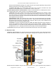
Step 3. Remove the wire strain relief bar on sensor terminal side of controller.
Step 4. Connect the red collector sensor wire to T1 terminals (red and white wires).
Connect grey storage tank sensor to T2 terminals (brown and white wires).
Step 5. Replace wire strain relief bar.
NOTICE
Do not install the sensor wires in direct contact with system pipes. Route sensor wires on
the outside of system pipe insulation when ever possible.
d) Sensors wires can be fed through the pump station and out the top to run along the collector return pipe
or out the bottom along the tank return pipe (OUTSIDE THE INSULATION).
e) Once all wires are connected to the controller and the strain relief bar screwed into place the cover can
be replaced.
8.7. Pump Operation
a) Fixed Speed Operation: The Apricus direct flow pump station is supplied standard with a single speed
Grundfos pump. In most domestic installs this standard pump will have sufficient head pressure. See the
performance curve to the right.
See pump specification sheet in Appendix 8.
i) Measuring Flow Rate: By utilizing the flow meter above the pump, the flow can be monitored. The
system flow rate can be adjusted by turning the flow restrictor screw (5/32” or 4mm Allen) on the flow
meter.
ii) Nominal Flow Rate: The recommended nominal flow rate for Apricus evacuated tube solar
collectors is 0.026 G/tube/min or 0.1 L/tube/min. Refer also to section 3.5.
b) Variable Speed Operation (recommended): The Apricus Controller allows for variable speed control of
the Grundfos pump. Refer to section 6.4 for programming details.
i) Flow Rate: When using variable speed control the full speed flow rate should be no more than 1.3
gpm / 5 lpm per 30 tube collector. The restrictor screw on the flow meter can be used to adjust the
flow rate to a suitable level.
ii) Speed Setting: Initially set the “Min rev pump” value to 50%, then manually test the pump operation
(Operation Menu) at this level and monitor the flow rate. The flow rate at the slowest pump operation
level should be around 40-50% of the full flow rate. Adjust the “Min rev pump” until a suitable flow rate
is achieved. 30% is the minimum possible setting.
ii) Operation: The pump will operate between the dTMax and dTMin temperature range, switching on
at 100% when dTMax is reached, and reaching minimum pump speed at dTMin. If dTMin is under-run,
the pump will switch off. If a slow enough flow rate is not able to be achieved with the “Min rev pump”
setting, reducing the dTMin down to 2-3
°
F (if not already) will help to prevent the pump cycling on and
off throughout the day.
c) Check Valve: All Apricus pump stations are supplied with the pump check valve installed.
8.8. Fill System
a) The Apricus direct flow pump station is designed to fill using the domestic water system pressure.
Apricus Solar Collector Installation & Operation Manual - USA
Copyright © 2011 – Apricus Inc Doc: A7-05.4.12-PB Page 66 of 129