AN D L ENERGY • • O TA L N TO Installation, Operation & Maintenance Manual IRONMENTA RSH I P DE Model UCR 30, 50 and 70 tons V EN A LE Remote Air Cooled Ultimate Chiller Solution GR EEN SOL UT I
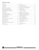
Table of Contents Introduction . . . . . . . . . . . . . . . . . . . . . . . . . . . . . . . . . . . . . . . . . 3 Startup . . . . . . . . . . . . . . . . . . . . . . . . . . . . . . . . . . . . . . . . . . . . .40 Pre-Installation . . . . . . . . . . . . . . . . . . . . . . . . . . . . . . . . . . . . . . . 4 Split System Startup . . . . . . . . . . . . . . . . . . . . . . . . . . . . . . . . . 42 Unit Installation . . . . . . . . . . . . . . . . . . . . . . . . . . . . . . . . . . . .
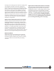
Introduction General Description WARNING: Indicates potentially hazardous situation which, if not avoided, could result in death or serious injury. The UCR configurable remote air cooled modular chiller, The Ultimate Chiller Solution®, is designed to provide the most environmentally friendly, maneuverable, efficient, reliable and serviceable modular chiller in the industry.
Pre-Installation Unit Installation Inspection Foundation for Unit Placement Upon receipt of equipment, carefully check the shipment against the bill of lading and inspect each chiller for any damage incurred during shipment. Thoroughly check for any visible damage of control panels and electrical and/or refrigeration components or broken copper lines.
into the groove of either pipe end. Place the coupling halves over the gasket and make sure that the coupling keys, the part that goes into the groove, are engaged into the grooves. Insert the bolts and install nuts to hand tight. Make sure that the oval neck of the bolt engages into the bolt hole of the housing. Tighten nuts alternately and equally until the bolt pads meet and make metal to metal contact.
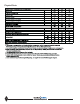
Physical Data 6 www.climacoolcorp.
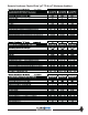
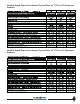
Remote Condenser Physical Data: 30°F TD & 110°F Maximum Ambient 7 www.climacoolcorp.
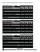
Remote Condenser Physical Data: 20°F TD & 120°F Maximum Ambient 8 www.climacoolcorp.
Variable Speed Remote Condenser Physical Data: 30°F TD & 110°F Maximum Ambient Variable Speed Remote Condenser Physical Data: 20°F TD & 120°F Maximum Ambient 9 www.climacoolcorp.
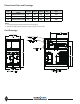
Dimensional Data and Drawings $ % $ % 2 $ % $ "% +( *(0#*+(#,.(#-/-#+#.( --; +,< .-2#6 ))/( )*.- -( *(0#*+(#,.(#-/-#+#.( --; +,< .-2#6 )/0- )1,- /( *(0#*+(#,.(#-/-#+#.( --; +,< .-2#6 )1*- *(0- ! Unit Drawings 10 www.climacoolcorp.
Rigging and Lifting Procedures Rigging (Figures 1 and 2) Each module should be lifted by using lift straps threaded through the steel base cut outs and the use of a spreader bar. Figure 1 Figure 2 Lifting and Transporting Modules (Figure 3) Pallet jacks or forklifts are required for lifting and transporting the module. Each module has base cutouts provided for ease of maneuverability. 11 www.climacoolcorp.
Mounting Rail and Vibration Isolation ClimaCool recommends locking down the chiller to a concrete base or to three 4” base mounting rails using the six bolt holes provided in each base pan. Due to the low vibration of the modules, ClimaCool does not require the application of spring isolators or pads. Should isolators or pads be desired install in accordance with Figures 1 and 2.
Recommended Service Clearances and Bank Dimensions Service Clearances Notes: 1. Allow 36” clearance for electrical panels and 30” clearance for rear access to modules. 2. Allow a minimum of 18” height clearance for service. 3. Local building or electrical codes may require additional clearance. Consult applicable codes.
Water Piping As with any water system, it is important that the system be clean. If care is taken during installation, the possibility of dirt related problems are avoided in future operation of the chiller. The pipe work installer must remove weld scale, rust and contamination during pipe work fabrication. The system water piping must be flushed thoroughly with recommended alkaline flush or other chemicals that are compatible with 316 stainless steel, prior to making connections to the ClimaCool chiller.
Notes: 1. Figures 1 and 2 are required piping for proper water regulation and distribution through ClimaCool modular chillers. 2. Module order and incoming/outgoing water flow, as shown in both Figure 1 and 2, can be set up as either a left-to-right or right-to-left configuration. 3. For chilled water (evaporator) inlet/outlet location dimensions, refer to page 10 - Dimension Data and Drawings. 4.
Water Temperature Requirement and Hydronic Refrigeration Chilled Water Temperature Modules are designed for a leaving water temperature range from 40°F to 62°F. All cataloged modules can operate safely in this range without the need of special controls or glycol additives. Leaving water temperatures below 40°F can result in evaporator suction temperatures below the freezing point of water.
Filling the Water System It is imperative that the water systems are free from debris prior to initial operation. See page 18– Water Treatment for a comprehensive list of precautions. Filling, Purging and Leak Testing the System Cleaning the System We recommend the following sequence to properly clean the water systems: 1. Whenever possible, install a temporary bypass line between After the water system has been properly installed a visual inspection should be made to all joints for tightness.
Water Treatment Water quality is of the utmost importance for the proper care and maintenance of the modular chiller system. Proper water treatment is a specialized industry and we recommend consulting an expert in this field to analyze the water for compliance with the water quality parameters listed in Table 1. The material used in the ClimaCool chiller exposed to the water are type 316 stainless steel, pure copper, and carbon steel. Other materials may exist external to the ClimaCool chiller.
Evaporator Water Pressure Drop Charts 19 www.climacoolcorp.
Table 1 - Performance Adjustment Factors vs. Altitude vs.
Electrical Connection The compliance of the installation to relevant local and national codes is the responsibility of the installer. Before carrying out any electrical work, confirm that the main supply is isolated. The installer must ensure that the correct electrical drawing is available. Before power is applied to the system, the wiring should be visually inspected for loose connections or grayed terminal connections.
Proper Voltage Balance Voltage/Phase Monitor Occasionally, in three phase circuits, a voltage imbalance occurs between phases. It is not recommended to operate equipment when an imbalance greater that 2% occurs. This causes motors to run at high temperatures and may affect their longevity. The following example describes how to calculate the average voltage of the three phases to see if the imbalance is greater than 2%.
Remote Condenser Low Ambient Control Location Standard at or above 45°F • Mechanical head pressure fan cycling on all fans. It is vital to select a suitable location for your remote air cooled condenser in order to allow sufficient air flow into the cavity of the condenser.
Head Pressure Control Valve Operation (LAC-10) High and Low Ambient Stability LAC-10 Valve Operation The design of air conditioning systems, utilizing air cooled condensing units, involves two main problems that must be solved if the system is to operate reliably and economically high ambient and low ambient operation. If the condensing unit is properly sized, it will operate satisfactorily during extremely high ambient temperatures.
Brazing Procedures for Head Pressure Control Valve Any of the commonly used brazing alloys for high side usage are satisfactory. However, when soldering or brazing, it is very important that the internal parts be protected by wrapping the valve with a WET cloth to keep the body temperature below 250°F for the LAC. Also, when using high temperature solders, the torch tip should be large enough to avoid prolonged heating of the copper connections. And, always direct the flame away from the valve body.
this must be taken into consideration. This is necessary since as the compressor unloads, the condenser’s capacity increases and additional flooding is required. Using the same roof mounted remote condenser as in the earlier example (40°F evaporator and minus 20°F minimum ambient), a multiplier of .79 is shown in Table 2. And since we have hot gas bypass (50%), this .79 is used to enter Table 3 to find a multiplier of .91.
Charging of Systems with Sporlan Head Pressure Control in Ambient ABOVE 70°F (After normal evacuation procedures) Before Starting System: 1. Connect refrigerant cylinder to a charging or gauge port on the receiver outlet valve. 2. Open the receiver valve approximately one-half way (so receiver and liquid line are connected to charging or gauge port). 3. Charge liquid refrigerant into the high side of the system. Weighing the charge is recommended with the initial charge consisting of approximately 2.
Malfunction – Low Head Pressure Chart 3RVVLEOH &DXVH 5HPHG\ $GG UHIULJHUDQW ,QVXIÀFLHQW UHIULJHUDQW FKDUJH WR DGHTXDWHO\ ÁRRG FRQGHQVHU /$& IDLOV WR FORVH GXH WR 6HH %HORZ D )RUHLJQ PDWHULDO LQ YDOYH D &DXVH /$& WR RSHQ E\ UDLVLQJ FRQGHQVLQJ UHFHLYHU SUHVVXUH DERYH YDOYH VHWWLQJ E\ F\FOLQJ FRQGHQVHU IDQ ,I
www.climacoolcorp.
Condenser Layout for RC1-007A*H24 and RC1-008A*H24, 1-Row, 2-Fan, 1140RPM 30 www.climacoolcorp.
Condenser Layout for RC2-019A, 026A and 31A*H48 and RC2-038A*H44, 2-Row, 4-Fan, 1140RPM 31 www.climacoolcorp.
Condenser Layout for RC2-018A*X48, RC2-026A*X40 and RC2-032A*X44, 2-Row, 4-Fan, 830 RPM 32 www.climacoolcorp.
Condenser Layout for RC2-014A*Q48, RC2-017A*Q42, RC2-021A*Q48 and RC2-025A*Q44, 2-Row, 4-Fan, 540 RPM 33 www.climacoolcorp.
Condenser Layout for RC2-020A*V48, RC2-025A*V42, RC2-033A*V42 and RC2-038A*V42, 2-Row, 4-Fan, Variable Speed 34 www.climacoolcorp.
Condenser Layout for RC2-047A*H62, RC2-046A*V60, RC2-032A*Q62, RC2039A*Q64, RC2-039A*X60 and RC2-047A*X62, 2-Row, 6-Fan 35 www.climacoolcorp.
Condenser Layout for RC2-048A*Q82, 2-Row, 8-Fan, 540RPM 36 www.climacoolcorp.
Pre-Startup All startups must be performed by ClimaCool factory trained personnel. Prior to chiller startup, there are certain essential checks which must be completed. Failure to carry out these checks could result in damage to the chiller voiding the modules warranty. Assembly ClimaCool recommends locking down the chiller to a concrete base, or to three 4” base mounting rails, using the six bolt holes provided in each base pan. Confirm that bolts have been properly tightened during installation. 1.
Chiller Pre-Startup Procedures 1. Turn selector switches inside the module starter/control 2. 3. panel (low voltage side) to the off position. For future reference write the circuit number and power panel identification inside of module control panel with a permanent marker. Ensure the correct fuses are installed in the control transformer fuse blocks inside each ClimaCool module. Turn on the power to each module. The “Power” light should be on.
Pre Start-Up Check List 39 www.climacoolcorp.
Startup All startups must be performed by ClimaCool factory trained personnel. Adjusting Unit Charge and TXV’s Using Superheat and Subcooling Method 1. Built into the logic of the CoolLogic Control System Due to varying installation conditions/applications and to optimize performance, proper refrigerant charge and TXV adjustment must be confirmed. 2. 3. 4. 5. 6. 7. is an anti-short cycle timer which will prevent the compressors from re-starting immediately following a compressor shutdown.
Caution: Do not charge to achieve subcooling temperature when the TXV is overfeeding. If the TXV is overfeeding, readings may still indicate low subcooling and low superheat, but circuit may not be undercharged.
Split System Startup Once installation is complete, check the following: • All refrigerant and electrical connections must be tight. Tighten all loose wire terminal connections that may have loosened in shipping. • The compressor oil is at the proper level in the oil sight glass for the compressor being used (See page 50 Compressor Information). • Check initial settings of thermostats and pressure controls.
www.climacoolcorp.
Circuit #2 Amperage 44 www.climacoolcorp.
Remote Condenser Warranty Agreement 45 www.climacoolcorp.
Remote Condenser Installation Guidelines Quarterly Chiller Operation and Maintenance Pressure and Temperature Log A log of temperatures and pressures should be taken regularly. Periodically conduct a visual inspection of the chiller to identify problems before they reach the point of failure. As with mechanical system, it is necessary to conduct a series of checks to the ClimaCool chiller to confirm correct operation. Check controller operating parameters and setpoints.
Heat Exchangers Draining When performing standard maintenance procedures such as flushing a heat exchanger, it will be necessary to close off a section of a module. This can easily be done if factory mounted water isolation valves are provided. Access to a floor drain is helpful when performing standard maintenance procedures. Back Washing It may become evident from the recorded weekly log data that the performance of the chiller is gradually degrading.
Figure 1 - City Water Cleaning Arrangement Connected to City Water Isolation Ball Valve (2”) Refrigerant Circuit #1 Service Port (3/4”) To Cooling Tower Header Refrigerant Circuit #2 From Cooling Tower Header Service Port (3/4”) Isolation Ball Valve (2”) Heat Exchanger To Drain Figure 2 - In Place Cleaning Arrangement Connected to City Water Cleaning Tank Isolation Ball Valve (2”) Refrigerant Circuit #1 Service Port (3/4”) To Cooling Tower Header Refrigerant Circuit #2 From Cooling Tower Header Cl
Operational Limitations & # ! 6*8)2 # ! # ! , - 96 & # ! # ! , - 586 # # , - 326 & # # , - 6:1 ! ' ! ' # & # # ! # , - 286 # * # # ! # , ' -, - 216 % $ ! #
Compressor Information The compressors used on the ClimaCool chiller are scroll compressors. They are highly efficient and extremely reliable. However, the information contained in this manual will be useful for their care. Compressor Rotation All scroll-type machines are unidirectional and will only compress in one direction. Operating in the reverse rotation can be destructive and will be indicated by a load operating noise together with a lack of compression.
Refrigeration Circuit Diagram FACTORY MODULE PIPING OF CHILLER MODEL # UCR030,050,070 FACTORYCHILLER WATER PIPING REMOTE AIR COOLED CONDENSER FIELD PIPING 14 15 CHILLER OUTLET W ATER MAIN (6") CHILLER INLET W ATER MAIN (6") 11 12 16 CONDENSER AIR EXHAUST 10 CHILLER W ATER OUTLET VALVE (WHEN USED) 8 (WHEN USED) S2 FLUSH SHUT-OFF VALVE CONDENSER FAN(S) 9 17 CHILLER W ATER INLET VALVE 18 S FILL SHUT-OFF VALVE 13 PETE'S PORTS 7 REFRIGERANT CIRCUIT#1 REFRIGERANT CIRCUIT#2 19 6 CONDENSER
Refrigeration System Re-Processing Conforming to local and national codes is the responsibility of the service technician or installing contractor. The service technician should be familiar with the following codes: • ASHRAE Standard Safety Code for Mechanical Refrigeration, ANSI/ASHRAE 15-1978 • American National Standard Code for Pressure Piping, ANSI B31.
Split System Interconnecting Piping Discharge Line Piping Recommendations All discharge lines should be kept as short as possible and the line sizing is determined to provide for a low-pressure drop. There should always be a gradual negative elevation change when traversing from the remote condenser location to the UCR module section. Avoid any reversing elevation changes throughout this discharge line run.
Refrigerant Charging Procedure Refrigerant Charging Once leak testing and evacuation are complete, refrigerant charging may commence. Always refer to the unit nameplate and guidelines within this section in order to establish the quantity of refrigerant required. IMPORTANT: Always introduce refrigerant into a system using a charging manifold with gauges, along with a refrigerant scale to accurately weigh the refrigerant cylinder throughout the entire charging process.
Table 1 – UCR030 Additional Refrigerant ' " $ 496& % .+* $ ! % 1."2 2+"2 22"2 11"2 2."3 3+"3 2*"3 21"3 3.
Sequence of Operation Generic Interface Chiller shall be enabled locally or remotely via selector switch on the face of the CoolLogic Master Control Panel from enable/disable contact by Building Automation System (BAS). Pumps for chilled water supply shall be started by others. When proof of flow is established in the chilled water lines, the ClimaCool chiller shall start.
Factory Installed Options Water Isolation Valves and Flush Ports 1. After unpacking your strainer, carefully inspect your Water isolation valves provide isolation to the module for maintenance and cleaning of evaporator heat exchanger, without increasing unit or bank dimensions, while adjacent modules continue normal operation. Optional choice of integral manual or motorized valves includes 3/4” fill and flush valves. 2.
Torque Specifications Clamped Lid Models: CS strainer models 3CS and 4CS have “over-center latch clamp” lid designs. The over-center clamp does not require adjustment when installing or removing the lid. The lock washer is set at the factory for proper clamp compression and normally requires no field adjustment. Minor tightening may be necessary over time. The lids are installed as follows: 1. Place the clamp around the strainer lid. 2.
Step 1. (Clamped Lid Models): remove the top of the strainer by taking off the band-clamp assembly.* Step 2. Lift the strainer element (conical screen) out of the strainer body. Step 3. Carefully scrub down the strainer element with a rigid nylon brush until all matter is loosened. Do not use a steel brush. Step 4. Wash the strainer element off with clean water. It is preferable to use a hose with a significant amount of water pressure. Do not use a pressure washer. Step 5.
To Program the ATF Controller Figure 3 1. Plug the transformer into a 120-VAC outlet. 2. Insert the 12-VDC plug coming from the transformer into the jack on the underside of the ATF box. 3. Test for power by pressing the manual flush side of the 4. 5. Figure 4 6. control switch (lower switch light should come on the valve will start to open). Adjust the “ON TIME” (Valve Open) by turning the inner timer ring with the GREEN POINTER clockwise to increase duration.
TroubleshooƟng for ATF Package Problem SoluƟon • Valve is leaking past ball • Seals damaged or worn out • Install repair kit • Valve is not stopping at proper closed posiƟon • Adjust limit switches • Valve Stem leaks • Worn stem seals • On metal valves: Ɵghten stem packing nut 1/2 turn. CAUTION! Over Ɵghtening stem nut could cause drag on motor and trip internal circuit breaker. May require repair kit or new valve.
Y Type and Basket Type Strainers Strainer Installation Instructions Maintenance Instructions 1. Ensure all machined surfaces are free of defects and For maximum efficiency determine the length of time it takes for the pressure drop to double that in the clean condition. Once the pressure drop reaches an unacceptable value, shut down line and follow the Strainer Removal Instructions above.
Electrical Data UCR Power Wiring - per Module Ultimate Model Type Ultimate Model # UCR030 UCR030AHASAC00S Voltage Internal Wiring - per Compressor Rated Min.Cir. MaxFuse Rec. Discon. Rated Min.Cir. Locked MaxFuse Rec. Load Amps Size Fuse Switch Load Amps Rotor Size Fuse4 Amps1 (MCA)2 (MOP)3,8 Size4,8 Size9 Amps1 (MCA)2 (LRA)5 (MOP)3 Size 208V-230V/ 3PH/ 60HZ 114 128 175 150 175 57.0 71.
Power Distribution Drawing Independent 115volt Power Supply Breaker Panel 1 115volt to Power Alarm For Optional Alarm Package CS Series Strainer .
POWER SUPPLY 460V POWER SUPPLY 460V 500VA TRANSFORMER ONLY MODULE MICRO CONTROLLER/ SENSOR PANEL Gnd Over ARCNET 156 Baud LON INTERFACE J1 10's OFF ON - MODULE MICRO CONTROLLER 0-10V RTD Therm Dry 0-20mA Even Odd 1N07 1N04 1N06 1N03 1N05 1N02 +5V J9 Mode Select J4 20 19 18 17 16 15 14 13 12 11 10 9 8 7 6 5 4 3 2 1 12 11 10 9 8 7 6 5 4 3 2 1 A06 A05 A04 A03 10V O N A02 1 2 3 4 Gnd 5 6 7 Xnet- Xnet+ 20 19 18 17 16 15 14 13 12 11 10 9 8 7 6 5 4 3 2 1 J16 J10 1N01 01 20 19 18 17
DESCRIPTION 66 www.climacoolcorp.com 60 6 0.8 0.7 CCFB5 FB1, FB2 CCFB3 CCFB4 CCFB5 UCR070AH... UCR070AN... UCR070AF... Fuse or C/B Name Fuse or C/B VAC 24 575 6 0.8 0.7 CCFB4 CCFB5 575 575 70 CCFB3 CCFB4 FB1, FB2 24 460 CCFB3 460 12 1.5 FB1, FB2 1.0 460 90 CCFB4 CCFB5 24 208-230 208-230 15 4.0 2.0 CCFB3 208-230 225 CCFB5 CB1, CB2 Fuse or C/B Amp Rating 575 24 575 70 6 0.8 1.0 575 460 24 460 460 15 4.0 2.
Troubleshooting Guide WARNING! The troubleshooting guidelines recommended in this section could result in exposure to electrical safety hazards. Please refer to the safety warnings provided in this manual. Failure to follow all of the recommended safety warnings provided could result in death or serious injury. When possible, disconnect all electrical power including remote disconnects before servicing. Follow proper lockout-tagout procedures.
www.climacoolcorp.com forms\ccool\standard forms\word files\warranty certificate 05-10.doc Please refer to the CC Installation, Operation and Maintenance manual for operating and maintenance instructions. NOTE: Some states or Canadian provinces do not allow limitations on how long an implied warranty lasts, or the limitation or exclusion of consequential or incidental damages, so the foregoing exclusion and limitations may not apply to you.
L ENERGY RSH I P DE AN D IRONMENTA A LE V EN • • N TO I O TA L GR EEN SO T LU ISO 9001:2000 Certified Quality: First & Always 7300 S.W. 44th St. Oklahoma City, OK 73179 Phone: 405-745-3185 Fax: 405-745-2072 www.climacoolcorp.com ClimaCool works continually to improve its products. As a result, the design and speci cations of each product at the time for order may be changed without notice and may not be as described herein.