
Manual

23
www.climacoolcorp.com
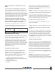
Remote Condenser
Location
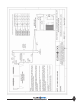
It is vital to select a suitable location for your remote air
cooled condenser in order to allow suffi cient air fl ow into
the cavity of the condenser. It is important not to place the
condenser into a “pit”, unless the pit is not any deeper than
the condenser height plus 10 feet, and there is at least a
clearance of 2 times the width of the unit on both sides in
between the condenser and the pit walls. The unit must also
be level in relation to the pit opening. Multiple units can be
placed next to each other, side by side, as long as there is
at least one width distance between them, that being the
width of the largest unit.
1”
Min.
W”
Min.
W”
Min.
Condensers can be located near fences, as long as there is
approximately 50% free area in the fence and the unit is no
closer than one width distance from the fence.
Multiple units can be placed next to each other, side by
side, as long as there is at least one width distance between
them, that being the width of the largest unit.
Control Panels
Factory assembled fan cycling control panels are available
to cycle fans for head pressure control either on ambient
temperature or condensing pressure. Contact ClimaCool for
custom applications for fan speed control or customer built
control panels.
• All fans are cycled with contactors.
• Condensers with a single row cycle fans separately with
one contactor per fan (e.g. Model #RC1-008A).
• Condensers with two rows of fans will have each row of
fans dedicated to one specifi c refrigeration circuit. Since
the fans closest to the header (or lead) end of the unit
run continuously, the second fan in each row will cycle
independently to control head pressure corresponding
to the circuit it serves.
• Standard control circuit voltage is 24 volts. Optional
control circuit voltages of 230 or 115 volts are available
upon request.
• Standard control circuits require an external power
supply for powering control circuit (by others).
• Optional factory mounted control circuit transformer
is available on 460 volt condenser fan motor voltage to
provide power to the control circuit.
Low Ambient Control
Standard at or above 45°F
• Mechanical head pressure fan cycling on all fans.
Optional +20°F
• Variable speed control furnished for lead fans.
• Mechanical head pressure fan cycling control provided
for on all others.
Optional -20°F
• Factory furnished, fi eld installed LAC-10 fl ooded head
pressure control valves required for each circuit.
• Condenser fans are provided with ambient temperature
fan cycling control.
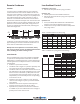
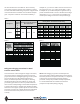
Number of Fans Design Temperature Diff erential °F
Single
Row
Double
Row
30° 25° 20° 15° 10°
2 4 35° 45° 55° 60° 70°
3 6 15° 30° 40° 55° 65°
4 8 0° 15° 30° 45° 60°
5 10 0° 10° 20° 35° 55°
6 12 0° 0° 10° 30° 50°
Table 1 - Minimum ambient for Fan Cycling
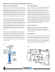
Number of Fans Design
Temperature
Diff erential °F
Thermostat Setting
Single Row Double Row
123
24
30° 60°
25° 65°
20° 70°
15° 75°
10° 80°
36
30° 60° 40°
25° 65° 55°
20° 70° 60°
15° 75° 65°
10° 80° 65°
48
30° 60° 50° 30°
25° 65° 55° 40°
20° 70° 65° 50°
15° 75° 70° 60°
10° 80° 75° 70°
Table 2 - Ambient Fan Cycling Thermostat Settings