
Instruction manual

THE SMART SOLUTION FOR ENERGY EFFICIENCY
D (ERV) Series
Rev.: 04 April, 2014
3
climatemaster.com
Installation
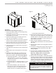
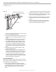
Fresh Air Hood Assembly (See Figure 1)
1. Secure hood sides (A and C) to Hood top (B) using
the supplied #10 x ½ screws.
2. Secure fi lter channels (F and D) to hood sides using
the supplied #10 x ½ screws.
3. Secure hood bottom (E) to the inside of the hood
sides using the supplied #10 x ½ screws.
4. Slide the fresh air fi lter (H) into the tracks created by
the front of the hood sides and the fi lter channels.
5. Secure the fi lter panel (G) to the hood sides. Slide the
fi lter panel under the front fl ange of the hood top.
6. Install fresh air hood over ERV fresh air opening on
front door panel.
7. Install barometric exhaust hood over exhaust blower
outlet.
8. Remove ERV control access panel to connect fi eld
wiring.
9. Route class II low voltage wire (3 conductor) from
thermostat or energy management through small
bushing in end panel of ERV. See wiring diagram.
a. Thermostat (dependent) - connect in parallel at
rooftop unit with “G”, “C” and “W”. Then connect
matching color at terminal 1, 2, and 3 respectively
on ERV circuit board.
b. Energy Management - provide +24 VAC to “1” and
common, 24 VAC to “2” terminals on ERV circuit
board.
c. Thermostat (dedicated) - splice into +24 vac
(blue wire) at (control circuit board) transformer
connection run wire to “R” terminal. Then run
another wire from “G” terminal to ERV (control
circuit board) terminal block #1.
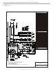
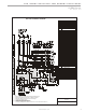
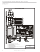
10. All electrical connections must conform to any local
codes and current National Electric Codes (NEC) and
Canadian Electric Codes (CEC). Refer closely to unit
wiring diagram in unit and/or in these instructions for
proper wiring connections.
11. Refer to the unit nameplate for minimum circuit
ampacity (MCA) and maximum overcurrent protection
size (fuse).
12. Electrical data is listed on unit rating plate and motor
name plates.
13. Connect line voltage power supply to ERV fuse block
in control box of unit from disconnect switch. See
wiring diagram.
14. Ground unit with a suitable ground connection either
through unit supply wiring or an earth ground.
Note: Unit voltage entries must be sealed
weather tight after wiring is complete.
15. Remove motor access panels. Locate belts fastened
to blower assembly. Install belt onto motor and blower
pulley. Adjust motor sheave to correct blower RPM for
CFM and external static pressure requirements. See
charts in this instruction. Multiple pulley arrangements
are available to meet the entire range.
(E)
(B)
(C)
(A)
(F)
(D)
(G)
(H)
ASSEMBLED FRESH AIR HOOD
Figure 1
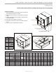
FORKLIFT CHANNELS
CAUTION!
CAUTION! Blower speed must be adjusted for the given
external static pressure and airfl ow (CFM) requirements. If
blower speed is not adjusted for conditions, possible motor
over loading can occur.