
Instruction manual

THE SMART SOLUTION FOR ENERGY EFFICIENCY
D (ERV) Series
Rev.: 04 April, 2014
5
climatemaster.com
Rotation Sensor
The circuit indicates the absence of pulses, within a
specifi ed time range, provided by a magnetic sensor
detecting a magnet mounted on wheel surface.
After the initial time delay of approximately 5 seconds
from circuit power up, if the sensor fails to provide a
signal pulse (no wheel rotation) within approximately 5
additional seconds, the alarm relay will activate and latch
(until circuit powers down) providing a 5 amp contact
closure output.
This would indicate no wheel rotation and/or magnet in
the system has stopped at the magnetic sensor pickup
point. If the pulse (wheel rotation) is detected within the
approximately 5 second time period, the alarm relay will
remain open. No fi eld timing adjustment of any type will
be required.
Dirty Filter Switches
Provides indication (red light) of switch closure (fi eld
adjustable set point) when differential pressure across
the fi lter bank has increase to trip when 24 VAC is
applied to terminals.
Recovery Wheel Mode
On a thermostat call for blower operation in heating,
cooling or continuous blower, the ERW will rotate
between fresh air and exhaust air streams. Both the
fresh air and exhaust air blowers will also be operating to
overcome the air resistance of the ERV.
System Check
1. Disconnect main power.
2. Turn to “Cont” for blower operation on thermostat
controlled models.
3. Restore power to unit. Observe ERV wheel rotation
and both fresh air and exhaust air blowers will
operating.
NOTE: If Low ambient kit is used the jumper
between TB37-5 & TB37-6 should be removed.
Also if system check out is being conducted at
low ambient temperatures, technician should
be aware that this kit can cause system not to
operate.
4. Verify that the ERV (3) three phase blower motors
are phased sequentially ensuring correct rotation and
operation.
a. Disconnect power.
b. Reverse any two fi eld power leads to the ERV.
c. Reapply power.
5. Verify that both blower motors are operating under
their full load AMP rating (FLA). The FLA can be
found on each motor and the unit nameplate.
A. Return Damper Settings
(When tied into HVAC System)
Manually adjust position of fi eld installed dampers to
balance air fl ow.
B. Air Flow / Blower Speed Adjustment
Blower speed selection is accomplished by changing
the sheave setting on both fresh air and exhaust air
blowers. To set ERV for the required air fl ow (CFM),
the external static pressure applied to the ERV (duct
static) must be known. See the CFM vs External
Static Pressure chart for the appropriate unit to
determine the correct blower RPM for the specifi ed
CFM and External Static Pressure.
After blower speed adjustments have been made. Ensure
that when the belt is replaced it is tensioned correctly.
The motor mounting plate can be adjusted to tension the
belt. If using a belt tension checker, adjust the span to the
appropriate setting and check the belt defection force.
The belt defl ection force should be between 5-8 lbs or the
lowest tension at which the belt will not slip under peak
load conditions.
1. Disconnect main power to unit before making
adjustment to economizer and/or ERV unit.
2. Replace ERV control access cover.
3. Set thermostat to normal operating position.
4. Restore power to unit.
Maintenance
1. All motors use pre-lubricated sealed bearings; no
further lubrication is necessary.
2. Make visual inspection of motors, belts and wheel
rotating bearings during routine maintenance.
3. Eight pie-shaped segments, are seated on stops
between the segment retainer which pivots on the
wheel rim and secured to the hub and rim of wheel.
Annual inspection of the self cleaning wheel is
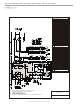
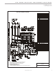
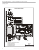
recommended. With power disconnected, remove
ERV access panels (rear) and unplug [J150 & P150]
(Refer to wiring diagram in this instruction
manual). Remove segment and wash with water and/
or mild detergent.
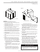
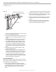
4. To install wheel segments follow steps A through
E . See Figure 2. Reverse procedure for segment
removal.