
Unit installation


44
ClimateMaster Water-Source Heat Pumps
CLIMATEMASTER WATER-SOURCE HEAT PUMPS
Tranquility
®
22 (TZ) Series
Revised: 05/12/15
Unit Start-up Procedure
1. Turn the thermostat fan position to “ON”. Blower
should start.
2. Balance air fl ow at registers.
3. Adjust all valves to their full open positions. Turn on
the line power to all heat pumps.
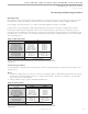
4. Room temperature should be within the minimum-
maximum ranges of table 9b. During start-up checks,
loop water temperature entering the heat pump
should be between 60°F [16°C] and 95°F [35°C].
5. Two factors determine the operating limits
of ClimateMaster heat pumps, (a) return air
temperature, and (b) water temperature. When any
one of these factors is at a minimum or maximum
level, the other factor must be at normal level to
ensure proper unit operation.
a. Adjust the unit thermostat to the warmest setting.
Place the thermostat mode switch in the “COOL”
position. Slowly reduce thermostat setting until
the compressor activates.
b. Check for cool air delivery at the unit grille within a
few minutes after the unit has begun to operate.
Note: Units have a fi ve minute time delay in
the control circuit that can be eliminated by
pushing the test button on the DXM2 control
board.
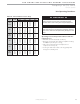
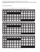
c. Verify that the compressor is on and that the water
fl ow rate is correct by measuring pressure drop
through the heat exchanger using the P/T plugs
and comparing to table 10.
d. Check the elevation and cleanliness of the
condensate lines. Dripping may be a sign of a
blocked line. Check that the condensate trap is
fi lled to provide a water seal.
e. Refer to table 12. Check the temperature of both
entering and leaving water. If temperature is within
range, proceed with the test. Verify correct water
fl ow by comparing unit pressure drop across the
heat exchanger versus the data in table 10. Heat
of rejection (HR) can be calculated and compared
to submittal data capacity pages. The formula for
HR for systems with water is as follows:
HR (Btuh) = TD x GPM x 500,where TD is the
temperature difference between the entering and
leaving water, and GPM is the fl ow rate in U.S.
GPM, determined by comparing the pressure drop
across the heat exchanger to table 10. In S-I units,
the formula is as follows: HR (kW) = TD x l/s x 4.18.
f. Check air temperature drop across the air coil when
compressor is operating. Air temperature drop
should be between 15
°F and 25°F [
8°C and 14°C].
g. Turn thermostat to “OFF” position. A hissing noise
indicates proper functioning of the reversing valve.
6. Allow fi ve (5) minutes between tests for pressure to
equalize before beginning heating test.
a. Adjust the thermostat to the lowest setting. Place
the thermostat mode switch in the “HEAT” position.
b. Slowly raise the thermostat to a higher
temperature until the compressor activates.
c. Check for warm air delivery within a few minutes
after the unit has begun to operate.
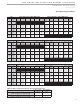
d. Refer to table 12. Check the temperature of both
entering and leaving water. If temperature is within
range, proceed with the test. If temperature is
outside of the operating range, check refrigerant
pressures and compare to table 11. Verify correct
water fl ow by comparing unit pressure drop across
the heat exchanger versus the data in table 10.
Heat of extraction (HE) can be calculated and
compared to submittal data capacity pages. The
formula for HE for systems with water is as follows:
HE (kW) = TD xGPM x 500, where TD is the
temperature difference between the entering
and leaving water, and l/s is the fl ow rate in U.S.
GPM, determined by comparing the pressure drop
across the heat exchanger to table 10. In S-I units,
the formula is as follows: HE (kW) = TD x l/s x 4.18.
e. Check air temperature rise across the air coil when
compressor is operating. Air temperature rise
should be between 20°F and 30°F [11°C and 17°C].
f. Check for vibration, noise, and water leaks.
7. If unit fails to operate, perform troubleshooting analysis
(see troubleshooting section). If the check described fails
to reveal the problem and the unit still does not operate,
contact a trained service technician to ensure proper
diagnosis and repair of the equipment.
8. When testing is complete, set system to maintain
desired comfort level.
Note: If performance during any mode appears
abnormal, refer to the DXM2 section or
troubleshooting section of this manual. To obtain
maximum performance, the air coil should be cleaned
before start-up. A 10% solution of dishwasher
detergent and water is recommended.
Unit Start-Up Procedure