Tranquility OA (TO) Series Table of Contents Model Nomenclature 3 General Information 4 Unit Connections and Service Clearances 4-15 Tons 7 Unit Connections and Service Clearances 20-30 Tons 8 Vertical Dimensional Data Model 04 & 05 9 Vertical Dimensional Model 08 & 10 10 Vertical Dimensional Data Model 15 11 Vertical Dimensional Data - Model 20-30 12 Vertical Dimensional Model 04 & 05 13 Vertical With Damper Box Dimensional Data Model 20 - 30 Commercial Vertical Dedicated Outdoor Air Pac
CLIMATEMASTER WATER-SOURCE HEAT PUMPS Vertical DOAS R e v.
THE SMART SOLUTION FOR ENERGY EFFICIENCY Vertical DOAS R e v.
CLIMATEMASTER WATER-SOURCE HEAT PUMPS Vertical DOAS R e v. : 0 1 / 3 1 / 1 3 General Information Safety Warnings, cautions, and notices appear throughout this manual. Read these items carefully before attempting any installation, service, or troubleshooting of the equipment. CAUTION: Indicates a potentially hazardous situation or an unsafe practice, which if not avoided could result in minor or moderate injury or product or property damage.
THE SMART SOLUTION FOR ENERGY EFFICIENCY Vertical DOAS R e v. : 0 1 / 3 1 / 1 3 Inspection - ClimateMaster DOAS units are not designed to support the weight of a person on all portions of the unit roof. Personnel should avoid stepping on the top of the unit. However, if it is necessary to stand on the roof, stay within 18” of the cabinet perimeter. ClimateMaster inspects and tests each DOAS unit before it leaves the factory so that you receive a quality piece of equipment.
CLIMATEMASTER WATER-SOURCE HEAT PUMPS Vertical DOAS R e v. : 0 1 / 3 1 / 1 3 Rigging - ClimateMaster DOAS units are solidly built and can be very heavy. Avoid personal injury and damaged equipment by planning the installation carefully. Use moving equipment whenever possible. Moving the DOAS Unit - Use hand trucks, equipment dollies or pipe rollers to move the DOAS Unit into place. Use caution so that the DOAS Unit does not tip over.
THE SMART SOLUTION FOR ENERGY EFFICIENCY Vertical DOAS R e v. : 0 1 / 3 1 / 1 3 Unit Connections and Service Clearances 4-15 Tons TOV 4-15 Tons Utility Location Electrical Access See Drawing Service Access Primary Side & Left Side Filter Access Left Side Water Cooled Piping Connection(s) Left (See Drawing) Condensate Drain Left (See Drawing) Notes: 1. Primary Side Access: 4 & 5 HP Units require 3’ - 0” clearance due to electrical panel.
CLIMATEMASTER WATER-SOURCE HEAT PUMPS Vertical DOAS R e v. : 0 1 / 3 1 / 1 3 Unit Connections and Service Clearances 20-30 Tons TOV 20-30 Tons Utility Location Electrical Access Primary Service Side Service Access Primary Side & Left Side Filter Access Left Side Water Cooled Piping Connection(s) Left (See Drawing) Condensate Drain Left Side Notes: 1. Primary Service Side Access require 3’ - 0” clearance due to electrical panel. 2.
c l i m a t e m a s t e r. c o m LEFT SIDE (SERVICE ACCESS) VIEW 3.44 Y Z 28.48 X 24.96 24.82 OUTLET 1 3/8" O.D. INLET 1" I.D. OUTLET CONDENSATE DRAIN CONNECTION RIGHT SIDE VIEW (NO ACCESS) 32.09 WIDTH** 38.95 OVERALL WIDTH 10.47" 110-10 W 13.60" 110-4 BLOWER MODEL 1 3/8" O.D. WATER COOLED AND HEAT PUMP CONDENSER CONNECTIONS FRONT SIDE (O/A INTAKE) VIEW DISCHARGE VIEW W ** ADD APPROXIMATELY 0.5 IN. FOR EXTERIOR PANEL FASTENERS * APPROXIMATE DIMENSION NOTES: 1.
LEFT SIDE (SERVICE ACCESS) VIEW C l i m a t e M a s t e r Wa t e r - S o u r c e H e a t P u m p s 4.47 ELECTRICAL ENCLOSURE LOCATION Y Z DISCHARGE VIEW 38.94 X 29.96 24.82 W 19.60" 16.47" BLOWER MODEL 110-4 110-10 OUTLET 1 3/8" O.D. INLET 1 3/8" O.D. 1" I.D. OUTLET CONDENSATE DRAIN CONNECTION RIGHT SIDE VIEW (NO ACCESS) 35.09 WIDTH** 41.95 OVERALL WIDTH WATER COOLED AND HEAT PUMP CONDENSER CONNECTIONS FRONT SIDE (O/A INTAKE) VIEW W ** ADD APPROXIMATELY 0.5 IN.
THE SMART SOLUTION FOR ENERGY EFFICIENCY Vertical DOAS R e v. : 0 1 / 3 1 / 1 3 Vertical Dimensional Data Model 15 Vertical 15 Ton Cabinet 51.19 27.98 LEFT SIDE (SERVICE ACCESS) VIEW NOTES: 1. FRONT OF UNIT LOOKING INTO OUTDOOR AIR INTAKE, WATER CONNECTIONS LEFT SIDE ONLY. * APPROXIMATE DIMENSION Z Y 4.47 ELECTRICAL ENCLOSURE LOCATION W X 38.94 DISCHARGE VIEW FRONT SIDE (O/A INTAKE) VIEW 39.50 29.93 1 5/8" O.D. INLET 1 5/8" O.D.
C l i m a t e M a s t e r Wa t e r - S o u r c e H e a t P u m p s RIGHT SIDE VIEW 11.000* * APPROXIMATE DIMENSION 7.565 5.000* Vertical 20-30 Ton LH Access 8.625 7.000* OPTIONAL CONDENSATE DRAIN LOCATION ELECTRICAL COMPARTMENT LEFT-HAND ACCESS ELECTRICAL ENTRY 10.840 40.000 BACK PRIMARY SERVICE ACCESS VIEW 77.250 OVERALL LENGTH TOP DISCHARGE VIEW 11.000* 60.000 DISCHARGE OPENING 11.000* 61.519 OVERALL WIDTH Part Based On Finish Material LEFT SIDE SERVICE ACCESS VIEW 2.625* 54.
THE SMART SOLUTION FOR ENERGY EFFICIENCY Vertical DOAS R e v. : 0 1 / 3 1 / 1 3 Vertical Dimensional Model 04 & 05 Vertical 4-5 Ton & Mixing Box 36.19 22.98 LEFT SIDE (SERVICE ACCESS) VIEW NOTES: 1. FRONT OF UNIT LOOKING INTO OUTDOOR AIR INTAKE, WATER CONNECTIONS LEFT SIDE ONLY. * APPROXIMATE DIMENSION DISCHARGE VIEW Z Y ** ADD APPROXIMATELY 0.5 IN. FOR EXTERIOR PANEL FASTENERS W X FRONT SIDE (O/A INTAKE) VIEW INLET 1 3/8" O.D.
CLIMATEMASTER WATER-SOURCE HEAT PUMPS Vertical DOAS R e v.
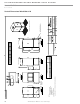
THE SMART SOLUTION FOR ENERGY EFFICIENCY Vertical DOAS R e v. : 0 1 / 3 1 / 1 3 Vertical Dimensional - Model 08 & 10 Vertical 8-10 Ton & Mixing Box 51.19 27.98 Z W X FRONT SIDE (O/A INTAKE) VIEW 1 3/8" O.D. INLET 1 3/8" O.D. OUTLET WATER COOLED AND HEAT PUMP CONDENSER CONNECTIONS Y ELECTRICAL ENCLOSURE LOCATION DISCHARGE VIEW LEFT SIDE (SERVICE ACCESS) VIEW NOTES: 1. FRONT OF UNIT LOOKING INTO OUTDOOR AIR INTAKE, WATER CONNECTIONS LEFT SIDE ONLY.
LEFT SIDE (SERVICE ACCESS) VIEW C l i m a t e M a s t e r Wa t e r - S o u r c e H e a t P u m p s ELECTRICAL ENCLOSURE LOCATION DISCHARGE VIEW X FRONT SIDE (O/A INTAKE) VIEW W OUTLET 1 5/8" O.D. INLET 1 5/8" O.D. WATER COOLED AND HEAT PUMP CONDENSER CONNECTIONS Y ** ADD APPROXIMATELY 0.5 IN. FOR EXTERIOR PANEL FASTENERS * APPROXIMATE DIMENSION NOTES: 1. FRONT OF UNIT LOOKING INTO OUTDOOR AIR INTAKE, WATER CONNECTIONS LEFT SIDE ONLY. 27.98 51.19 Vertical 15 Ton & Mixing Box 1" I.D.
THE SMART SOLUTION FOR ENERGY EFFICIENCY Vertical DOAS R e v. : 0 1 / 3 1 / 1 3 TO VF/VD Physical Data Table Model Fan motor available H.P. Blower wheel size 4 5 0.5/1.0/1.5/2.0 11-04/11-10 Compressor type/qty 8 10 0.5/1.0/1.5/2.0 0.5/1.0/1.5 0.5/1.0/1.5/2.0 11-04/11-10 11-04/11-10 11-10 Scroll, 1 ea. Scroll 2ea. (1 tandem set) Factory charge lb/unit HFC-410A Tranquility units Water Connection Size “ O.D.
CLIMATEMASTER WATER-SOURCE HEAT PUMPS Vertical DOAS R e v. : 0 1 / 3 1 / 1 3 Vertical Installation Condensate Piping – Vertical Units - The condensate drain connection is on the side of the DOAS unit. Pitch the drainpipe a minimum of 1/4 inch per linear foot, and support it at least every 5 feet. If the drain runs through an unconditioned space, you must install heat tracing to prevent the moisture in the drain from freezing.
THE SMART SOLUTION FOR ENERGY EFFICIENCY Vertical DOAS R e v. : 0 1 / 3 1 / 1 3 Duct System Installation Duct System Installation - Duct design and installations should conform to the latest ASHRAE and SMACNA low velocity duct standards Undersized, restrictive ductwork with abrupt turns or transitions can decrease the efficiency and the moisture removal capacity of your DOAS unit. Size the ductwork for an acceptable air pressure drop at the airflow volume of your DOAS unit.
CLIMATEMASTER WATER-SOURCE HEAT PUMPS Vertical DOAS R e v. : 0 1 / 3 1 / 1 3 Recommended Duct Designs - You must use proper duct design to ensure that the DOAS unit operates efficiently and without problems. Undersized or restrictive ducts reduce the system air flow which can cause premature compressor failure. Use the proceeding diagrams as a guide when you design the duct system.
THE SMART SOLUTION FOR ENERGY EFFICIENCY Vertical DOAS R e v. : 0 1 / 3 1 / 1 3 Figure 3: Recommended Duct Design for DOAS Units Recommended Not Recommended 30° or More 20° or Less Discharge Discharge Duct Turns 5W or More for Static Pressure Regain Intake Intake Duct Turns 2.5W or More Intake Intake Duct Turns c l i m a t e m a s t e r.
CLIMATEMASTER WATER-SOURCE HEAT PUMPS Vertical DOAS R e v. : 0 1 / 3 1 / 1 3 Piping Installation WARNING! WARNING! Polyolester Oil, commonly known as POE oil, is a synthetic oil used in many refrigeration systems including those with HFC-410A refrigerant. POE oil, if it ever comes in contact with PVC or CPVS piping, may cause failure of the PVC/CPVC.
THE SMART SOLUTION FOR ENERGY EFFICIENCY Vertical DOAS R e v. : 0 1 / 3 1 / 1 3 Water Quality Standards Table 2: Water Quality Standards Water Quality Parameter HX Material Closed Recirculating Open Loop and Recirculating Well Scaling Potential - Primary Measurement Above the given limits, scaling is likely to occur. Scaling indexes should be calculated using the limits below. pH/Calcium Hardness Method All - pH < 7.
CLIMATEMASTER WATER-SOURCE HEAT PUMPS Vertical DOAS R e v. : 0 1 / 3 1 / 1 3 Electrical Wiring - Line Voltage WARNING! WARNING! To avoid possible injury or death due to electrical shock, open the power supply disconnect switch and secure it in an open position during installation. CAUTION! CAUTION! Use only copper conductors for field installed electrical wiring. Unit terminals are not designed to accept other types of conductors.
THE SMART SOLUTION FOR ENERGY EFFICIENCY Vertical DOAS R e v. : 0 1 / 3 1 / 1 3 Electrical Wiring - Low Voltage Controls Wiring - Many of the controls and sensors in the ClimateMaster Tranquility DOAS units have been factoryinstalled and wired. However, you will have to make certain connections in the field.
CLIMATEMASTER WATER-SOURCE HEAT PUMPS Vertical DOAS R e v. : 0 1 / 3 1 / 1 3 Figure 6: Remote Room Sensor Figure 7: Remote Terminal This wall-mountable display is an IP30 rated device. Ambient conditions must be between 32.0ºF and 120.0ºF and less than 85% RH. The controller’s RS485 serial interface communicates via three-way plug-in terminals. Use a twisted pair plus shielded cable, 20-22 AWG. Total length of the network must not exceed 1,500 feet.
THE SMART SOLUTION FOR ENERGY EFFICIENCY Vertical DOAS R e v. : 0 1 / 3 1 / 1 3 Unit Starting & Operating Conditions Table 3: Operating Limits Table VF/VD Models Air Limits Cooling/Dehumid Mode Heating Mode Minimum Ambient Air 40ºF [4.4ºC] 40ºF [4.4ºC] Maximum Ambient Air 100ºF [37.8ºC] 100ºF [37.8ºC] Minimum Entering Air 50ºF [10.0ºC] 15ºF [-9.4ºC] Maximum Entering Air 110ºF [43ºC] 80ºF [26.7ºC] Minimum Entering Water 35ºF [1.7ºC] 35ºF [1.7ºC] Maximum Entering Water 105ºF [1.
CLIMATEMASTER WATER-SOURCE HEAT PUMPS Vertical DOAS R e v. : 0 1 / 3 1 / 1 3 System Start-up Report - A copy of the system start up report can be found in the back of this manual. This report needs to be filled out thoroughly by a qualified service technician and returned to ClimateMaster for warranty validation. Please ensure that the model and serial number of the unit is noted on this form.
THE SMART SOLUTION FOR ENERGY EFFICIENCY Vertical DOAS R e v. : 0 1 / 3 1 / 1 3 System Operation Modes Principle of Operation - Tranquility DOAS Units - The Tranquility DOAS unit conditions 100% outdoor air. Its refrigeration system extracts heat from, or rejects heat into a building loop or geothermal loop to maintain either the supply air or the space temperature. Its mode of operation depends on whether the outdoor air is above or below design conditions.
CLIMATEMASTER WATER-SOURCE HEAT PUMPS Vertical DOAS R e v. : 0 1 / 3 1 / 1 3 Tranquility systems equipped with this option are provided with a supply air and a room temperature sensor, a wall-mounted sensor housing, and a ductmounted sensor holder. See the housing and holder cut sheets for assembly and installation details. Mount the space sensor in an area where its accuracy will not be affected by drafts, hot spots, or solar gain.
THE SMART SOLUTION FOR ENERGY EFFICIENCY Vertical DOAS R e v. : 0 1 / 3 1 / 1 3 Service and Maintenance You can prevent many future problems by adhering to the recommended maintenance schedule shown. If you do discover a problem with the DOAS unit or the installation, refer to the TROUBLESHOOTING GUIDE. IF YOU HAVE EXHAUSTED THE TROUBLESHOOTING GUIDE AND HAVE NOT DISCOVERED THE PROBLEM, CALL THE CLIMATEMASTER SERVICE DEPARTMENT AT (405) 7456000.
CLIMATEMASTER WATER-SOURCE HEAT PUMPS Vertical DOAS R e v. : 0 1 / 3 1 / 1 3 Severe Burnouts • If the burnout is severe, recover the refrigerant charge or transfer it to an unused portion of the refrigeration circuit such as the receiver. You may need to energize the liquid line solenoid valve to evacuate the circuit completely. On systems equipped with an optional tower water condenser, take care to avoid freezing the condenser during evacuation.
THE SMART SOLUTION FOR ENERGY EFFICIENCY Vertical DOAS R e v.
CLIMATEMASTER WATER-SOURCE HEAT PUMPS Vertical DOAS R e v. : 0 1 / 3 1 / 1 3 Appendix Figure 9: System Rating Plate Figure 10: Model Numbering Matrix The system rating plate is attached to the outside of the electrical box door. You will need rating plate information when you install and service the DOAS unit.
THE SMART SOLUTION FOR ENERGY EFFICIENCY Vertical DOAS R e v. : 0 1 / 3 1 / 1 3 Service Bulletin DEDICATED OUTDOOR AIR SYSTEM (DOAS) Factory Pre-Commissioning Form, Pg. 1 Factory Commissioning of the DOAS system is required and is included in the sale of all DOAS units. Commissioning requires a ClimateMaster Service Dept.
CLIMATEMASTER WATER-SOURCE HEAT PUMPS Vertical DOAS R e v. : 0 1 / 3 1 / 1 3 Pre-Commissioning Form, Pg.
THE SMART SOLUTION FOR ENERGY EFFICIENCY Vertical DOAS R e v. : 0 1 / 3 1 / 1 3 Start-Up Report DEDICATED OUTDOOR AIR SYSTEM (DOAS) Commissioning Report, Tranquility and Genesis Series Heat Pumps, Pg. 1 IMPORTANT: For warranty validation and activation a copy of this form must be completed for each ClimateMaster DOAS unit and form must be returned to ClimateMaster Technical Service Dept. immediately after completion of commissioning.
CLIMATEMASTER WATER-SOURCE HEAT PUMPS Vertical DOAS R e v. : 0 1 / 3 1 / 1 3 Commissioning Report, Tranquility and Genesis Series Heat Pumps, Pg.
THE SMART SOLUTION FOR ENERGY EFFICIENCY Vertical DOAS R e v. : 0 1 / 3 1 / 1 3 Commissioning Report, Tranquility and Genesis Series Heat Pumps, Pg. 3 DOAS units have warm weather and cold weather modes of operation. Each mode MUST be tested and documented for warranty Validation. For additional information contact ClimateMaster Technical Service Dept. @ (800) 299-9747.
CLIMATEMASTER WATER-SOURCE HEAT PUMPS Vertical DOAS R e v.
c l i m a t e m a s t e r. c o m Rev.: 10/06 Please refer to the CM Installation, Operation and Maintenance Instruction for installation, operating and maintenance instructions. LC395 *LC395* NOTE: Some states or Canadian provinces do not allow limitations on how long an implied warranty lasts, or the limitation or exclusions of consequential or incidental damages, so the foregoing exclusions and limitations may not apply to you.
CLIMATEMASTER WATER-SOURCE HEAT PUMPS Vertical DOAS R e v.
THE SMART SOLUTION FOR ENERGY EFFICIENCY Vertical DOAS R e v. : 0 1 / 3 1 / 1 3 Notes: c l i m a t e m a s t e r.
CLIMATEMASTER WATER-SOURCE HEAT PUMPS Vertical DOAS R e v.